
An injection mold looks like a steel tool from the outside, but the inside is a working system of plates, inserts, runners, gates, cooling channels, ejector parts, vents, and moving components. Each part has a job. Some parts shape the plastic. Some control how resin flows. Some remove heat. Some release the finished part. Others keep the mold aligned after thousands or even millions of open-and-close cycles.
For buyers and product designers, these mold components are not just moldmaker terminology. They explain why one plastic part can use a simple open-and-shut mold, while another part needs slides, lifters, hot runners, special cooling, or replaceable inserts. Those choices affect mold cost, lead time, trial risk, part quality, and long-term production stability.
A small side hole on a plastic housing may look minor on the CAD model, but the mold may need a slide because of it. A deep boss may need stronger ejection support and better cooling. A cosmetic surface may need better cavity steel and more careful finishing. The buyer may only see one molded part, but the moldmaker sees parting lines, flow paths, cooling risks, ejection direction, steel movement, and maintenance needs.
This article breaks down the main injection mold components and explains what each one does in plain manufacturing language. The goal is not to turn every customer into a mold designer, but to make mold quotations, DFM comments, and tooling discussions easier to understand.
Quick Answer: What Are the Main Injection Mold Components?
The main injection mold components include the mold base, core, cavity, cavity plate, core plate, inserts, sprue, runner, gate, ejector pins, ejector plates, cooling channels, vents, guide pins, bushings, slides, lifters, and alignment components. These parts work together to form the plastic part, control material flow, remove heat, release the part, and keep the mold stable during production.
A simple mold may only need basic core, cavity, runner, gate, cooling, and ejector components. A complex mold may require slides, lifters, hot runner systems, replaceable inserts, wear plates, special venting, and advanced cooling features.
The right mold structure depends on plastic part geometry, material, tolerance requirements, surface finish, annual volume, and tooling budget. That is why two parts with similar size can have very different mold costs.
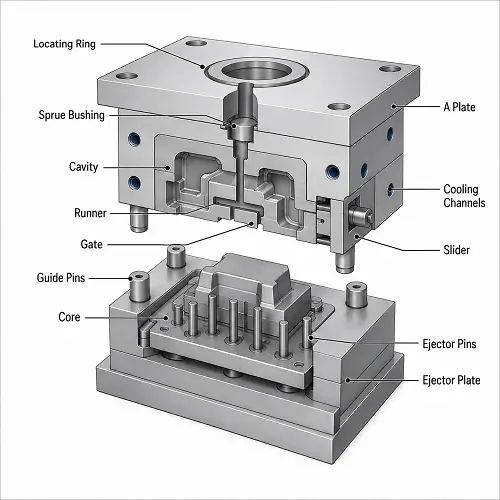
Injection Mold Diagram: How the Mold Parts Work Together
A basic injection mold has two main halves: the fixed half and the moving half. The fixed half is mounted to the stationary side of the injection molding machine. The moving half opens and closes with the machine clamp unit.
Molten plastic enters through the sprue, flows through runners and gates, and fills the cavity. The core and cavity shape the plastic part. Cooling channels remove heat from the mold steel. Vents allow trapped air and gas to escape during filling. After the part cools, the mold opens and the ejector system pushes the part out.
| Mold Area | Main Function |
|---|---|
| Fixed half | Holds the sprue side, cavity side, and machine mounting features |
| Moving half | Carries the core side and ejector system |
| Core and cavity | Shape the molded plastic part |
| Runner and gate | Deliver molten plastic into the cavity |
| Cooling channels | Remove heat and control cycle stability |
| Ejector system | Pushes the part out after cooling |
| Vents | Release trapped air and gas during filling |
| Slides and lifters | Form side holes, undercuts, and complex features |
A mold diagram is useful because many important mold components are hidden during production. The finished plastic part may look simple, but the mold may need careful internal structure to fill, cool, vent, and release that part reliably.
Common Injection Mold Structures
Injection molds can be built in different structures depending on part design, gate location, production volume, and cost target. The most common structures include two-plate molds, three-plate molds, and hot runner molds.
A two-plate mold is the simplest common mold structure. It has a fixed half and a moving half. The runner and part usually release from the same parting line. This structure is often used for simple parts, edge gates, direct gates, and many general production molds.
A three-plate mold adds an extra plate movement. This allows the runner system and molded part to separate at different levels. Three-plate molds can support more flexible gate placement, such as pinpoint gates, but the structure is more complex than a two-plate mold.
A hot runner mold uses heated manifold components to keep plastic molten until the material reaches the gate. Hot runners reduce runner waste and can improve production efficiency, especially in higher-volume production. The tradeoff is higher mold cost, more temperature control, and more maintenance.
A two-plate mold for a simple cover and a hot runner mold for a multi-cavity cosmetic part may both produce plastic parts, but the internal structure, mold cost, maintenance work, and trial risks are very different.
Mold Base Components
The mold base is the frame that holds the entire mold assembly together. It supports the core, cavity, plates, ejector system, guide components, cooling lines, inserts, and moving mechanisms.
A typical mold base may include the top clamp plate, cavity plate, core plate, support plate, spacer blocks, ejector plate, ejector retainer plate, and bottom clamp plate. These plates do not always touch the plastic part directly, but they carry the forces created by clamping, injection pressure, ejection, and repeated production cycles.
The top clamp plate mounts the fixed half of the mold to the machine platen. The cavity plate, often called the A plate, holds the cavity side or cavity inserts. The core plate, often called the B plate, holds the core side or core inserts. Support plates and spacer blocks create strength and space for the ejector system. The ejector plate moves ejector pins forward, while the ejector retainer plate holds those pins in place.
A cheap or undersized mold base can create trouble later. Poor support may lead to deflection. Weak alignment may cause flash or mismatch. Poor machine fit may create setup problems. Platen size, tie-bar spacing, mold height, clamp force, and opening stroke should all be reviewed before mold manufacturing.
Core and Cavity Components
The core and cavity are the main forming components of an injection mold. They directly create the shape of the molded plastic part.
The cavity usually forms the outside or appearance surface of the part. The core usually forms the inside geometry, such as ribs, bosses, holes, pockets, and hollow areas. In many molds, the plastic part shrinks onto the core side after cooling, so the ejector system is usually located on the core side.
Core and cavity components may include cavity inserts, core inserts, shutoff surfaces, parting line surfaces, and replaceable inserts. A cavity insert may form the outer surface of a cosmetic part. A core insert may form a deep boss or internal pocket. A shutoff surface may form a hole, slot, or opening without using a separate slide.
Core and cavity design affects part shape, surface finish, dimensional accuracy, shrinkage allowance, draft angle, and mold release. Poor core or cavity design can cause sticking, drag marks, flash, sink marks, dimensional error, or difficult ejection.
For cosmetic parts, cavity finish is especially important. Polishing, texture, EDM finish, and parting line placement can affect the final appearance. For tight-tolerance parts, core and cavity dimensions must also account for material shrinkage and possible steel-safe adjustment during mold trial.
Feeding System: Sprue, Runner, Gate, and Cold Slug Well
The feeding system delivers molten plastic from the injection molding machine into the mold cavity. In a cold runner mold, the feeding system usually includes the sprue, runner, gate, and cold slug well. In a hot runner mold, heated manifold components replace or reduce cold runner material.
The sprue bushing connects the machine nozzle to the mold. The sprue is the first main channel where plastic enters. The runner carries plastic from the sprue toward the cavity or cavities. The gate is the final opening where plastic enters the molded part. A cold slug well catches colder material at the flow front so that it does not enter the part surface too early.
Gate design is one of the most important details in the feeding system. A gate that is too small can create high pressure, short shots, early gate freeze, poor packing, or sink marks. A gate that is too large can leave a visible gate vestige or make trimming harder. Poor gate location can create weld lines, flow marks, air traps, or uneven shrinkage.
In multi-cavity molds, runner balance becomes important. If one cavity fills faster than another, part weight, dimensions, and quality may vary across cavities. Runner and gate design can affect filling, pressure loss, weld lines, gate marks, and packing behavior, so these details must match the part geometry, resin flow, wall thickness, cosmetic requirements, and production volume.
Ejection System Components
The ejection system removes the molded part from the mold after cooling. Since plastic often shrinks onto the core during cooling, the part usually needs controlled force to release cleanly.
Common ejection components include ejector pins, ejector sleeves, ejector blades, ejector plates, ejector retainer plates, return pins, stripper plates, and sometimes air assist. Ejector pins are the most common. Ejector sleeves are often used around bosses or round features. Ejector blades can help release narrow ribs or thin features. A stripper plate can distribute force over a larger area when pin marks must be reduced.
Ejection design affects part release, ejector marks, deformation, whitening, cracks, and cycle stability. If pins are too small, poorly placed, or not balanced, the part may show dents, pin marks, stress whitening, or bending.
Good ejection design starts with the plastic part design. Draft angle, rib depth, texture direction, core polish, and undercuts all affect how much force is needed to release the part. A molded part with poor draft may force the toolmaker to add more ejection force, but that can create visible marks or deformation.
Cooling System Components
The cooling system removes heat from the mold and helps control cycle time, shrinkage, and part stability. In many injection molding projects, cooling takes more time than filling and packing, so cooling design has a direct effect on production cost.
Cooling system components may include cooling channels, water connectors, baffles, bubblers, cooling plugs, O-rings, high-conductivity inserts, and conformal cooling inserts. Cooling channels carry water or coolant through the mold. Baffles redirect coolant flow in deeper areas. Bubblers help cool deep cores or narrow sections. High-conductivity inserts can improve heat removal in local hot spots. Conformal cooling follows the cavity contour more closely, often in complex inserts.
Cooling channels must be close enough to remove heat effectively, but not so close that mold strength is weakened. Poor cooling design can create hot spots, long cycle time, warpage, sink marks, and unstable dimensions.
Cooling is not only about running the mold faster. Stable cooling helps control shrinkage, flatness, and repeatability. A part that cools unevenly may pass visual inspection at first but fail later because of warpage or dimensional drift.
Venting System Components
The venting system allows trapped air and gas to escape as molten plastic fills the cavity. Without good venting, air becomes compressed at the end of flow. The result can be burn marks, short shots, flow hesitation, weak weld lines, or poor surface finish.
Venting can be built into the parting line, vent grooves, fitted inserts, ejector pin clearance, vent plugs, or porous venting inserts. The best venting method depends on where air is trapped and how the plastic flows through the cavity.
Vent depth must be controlled carefully. If vents are too shallow or blocked, air cannot escape. If vents are too deep, plastic can flash into the vent. This is one reason mold maintenance matters. Vents can become blocked by residue over time, especially in production molds running materials that release gas or additives.
Venting is especially important near the end of fill, around ribs, bosses, weld line areas, thin sections, deep pockets, and tight shutoffs. A mold can have good steel and good machining but still produce burn marks or short shots if trapped air has nowhere to go.
Guiding and Alignment Components
Guiding and alignment components help the mold halves open and close accurately. They protect the core and cavity from mismatch, impact, and uneven wear.
Common alignment components include guide pins, guide bushings, locating rings, interlocks, taper locks, and wear plates. Guide pins and bushings guide mold halves during opening and closing. The locating ring aligns the mold with the machine nozzle. Interlocks and taper locks improve precision alignment under molding pressure. Wear plates reduce damage in areas with sliding or repeated contact.
Poor alignment can cause flash, parting line mismatch, uneven wall thickness, mold damage, and premature wear. For molds with slides, lifters, shutoffs, or tight-tolerance geometry, alignment becomes even more important.
These components may not be visible on the molded plastic part, but they help keep production stable over time.
Slides, Lifters, and Side Action Components
Slides, lifters, and side actions are used when the plastic part has features that cannot be released straight in the mold opening direction. These features may include side holes, undercuts, snap hooks, grooves, clips, and lateral openings.
A slide moves sideways to form side holes or outside undercuts. A lifter moves at an angle to release internal undercuts or snap features. Angle pins often drive slide movement during mold opening and closing. Slide locks hold slides in position during injection. Wear plates support movement and reduce wear. Hydraulic cylinders may be used for larger or more complex side actions.
Slides and lifters increase mold complexity. They require additional machining, fitting, alignment, locking, lubrication, and maintenance. They can also increase mold size, mold cost, and cycle time.
A good DFM review should check whether side actions are truly necessary. Sometimes a small change to the plastic part can remove an undercut and simplify the mold. In other cases, side actions are required, and the mold must be designed with enough strength and wear resistance for production.
Mold Inserts and Wear Components
Mold inserts are removable components installed in the core or cavity. They are commonly used for detailed features, hard-to-machine areas, high-wear areas, or areas that may need adjustment after mold trial.
Core inserts can form internal details or deep features. Cavity inserts can form cosmetic or outer features. Replaceable wear inserts protect areas exposed to friction or abrasive materials. Shutoff inserts form holes, slots, or sealing details. Repair inserts allow localized correction without replacing a large mold plate.
Inserts can reduce maintenance cost and improve mold serviceability. If a small area wears or needs adjustment, the toolmaker may replace or modify an insert instead of remaking a large mold plate.
Wear components are especially important when molding glass-filled plastics, mineral-filled materials, or high-volume production parts. Abrasive materials can wear gates, runners, shutoffs, slides, and cavity details faster than unfilled resins.
Good insert design helps protect the main mold structure and makes long-term production easier to maintain.
How Injection Mold Components Affect Part Quality
Injection mold components directly affect molded part quality. A part defect is not always caused by the molding machine. Many defects begin with mold structure.
Core and cavity surfaces affect dimensions, texture, gloss, parting line, and draft. Runner and gate design affects filling, weld lines, pressure loss, gate marks, and packing. Cooling channels affect warpage, cooling time, shrinkage stability, and dimensional repeatability. Ejector components affect marks, whitening, bending, and part release. Vents affect burn marks, short shots, trapped gas, and weld line strength. Slides and lifters affect undercuts, side holes, flash risk, and maintenance stability.
For example, poor cooling may cause warpage even if the cavity is machined correctly. Poor venting may cause burn marks even if injection pressure is reasonable. Poor ejector layout may deform a part that otherwise fills and cools properly.
A good mold design reviews all components as a working system, not as separate pieces of steel.
How Injection Mold Components Affect Mold Cost
Mold cost depends heavily on component complexity. A simple open-and-shut mold is usually less expensive than a mold with slides, lifters, hot runners, conformal cooling, high-polish cavities, complex inserts, and tight shutoffs.
Slides and lifters add cost because they require moving mechanisms, fitting, locking, and wear control. Hot runner systems add manifolds, nozzles, heaters, temperature controllers, and maintenance requirements. Complex cooling adds machining time or special inserts. High-polish cavities require extra finishing and surface control. Hardened or premium steels improve durability but raise tooling cost.
A cheaper mold is not always the lowest-cost choice. If a low-cost mold causes long cycle time, frequent maintenance, poor cooling, flash, difficult ejection, or unstable dimensions, production cost can increase later.
Good mold component design balances tooling cost, part quality, cycle time, production volume, and maintenance.
Common Injection Mold Component Problems
Many molding problems can be traced to one mold component or one area of mold construction.
| Mold Component | Possible Problem | Part Quality Risk |
|---|---|---|
| Gate | Too small, wrong location, early freeze | Short shot, weld lines, sink marks, gate blush |
| Runner | Poor balance or excessive pressure loss | Uneven filling, cavity imbalance |
| Cooling lines | Too far from cavity or unbalanced | Warpage, long cooling time, dimensional drift |
| Ejector pins | Poor placement or excessive force | Ejector marks, whitening, deformation |
| Vents | Too shallow, blocked, or poorly located | Burn marks, short shots, gas traps |
| Slides and lifters | Poor fit, wear, weak locking | Flash, mismatch, maintenance issues |
| Core and cavity | Poor machining, bad draft, wear | Dimensional error, sticking, surface defects |
| Mold base | Weak support or poor alignment | Flash, mismatch, mold wear |
| Inserts | Poor fit or wrong material | Flash, wear, local dimensional problems |
This type of review helps customers understand why mold design must be checked before manufacturing. A small feature on the plastic part can affect several mold components at the same time.
Example: Why One Mold Component Can Change the Whole Tool Design
A plastic housing may look simple from the outside. If the part includes a side hole, snap feature, or internal undercut, the mold may need a slide or lifter instead of a simple open-and-shut structure. That one feature can change mold cost, mold size, maintenance requirements, and cycle stability.
The same logic applies to deep bosses or tall ribs. These features may need stronger ejection support, better cooling, or local inserts to avoid sink marks, sticking, or deformation. A small design detail can affect the core, ejector system, cooling layout, and insert strategy at the same time.
This is why DFM review matters before mold manufacturing. Mold components are not selected randomly. They are chosen based on plastic part geometry, material behavior, surface requirements, tolerance needs, and production volume.
Injection Mold Making Services and Mold Component Review
Understanding mold components is useful, but the real value comes from applying that knowledge to an actual plastic part. During mold design, each component must match the part geometry, resin, surface requirement, tolerance target, and production volume.
When JeekMould reviews a new molded part, the team does not only look at the outside shape. Mold structure has to be judged from the parting line, gate location, cooling path, ejection direction, undercuts, material shrinkage, cosmetic surface requirements, and expected production volume.
This review helps determine whether a part can use a simple open-and-shut mold or whether the design needs slides, lifters, special cooling, replaceable inserts, hot runner components, or a more complex mold structure. For production parts, this step can reduce mold trial corrections and improve molding stability.
If a part has undercuts, thin walls, thick bosses, cosmetic surfaces, tight dimensions, or difficult ejection areas, mold component review before tooling can save time and reduce risk. Customers who need injection mold making services or molded plastic part production can request an injection mold quote after submitting CAD files and basic project requirements.
FAQ: Injection Mold Components
What are the main components of an injection mold?
The main injection mold components include the mold base, core, cavity, inserts, sprue, runner, gate, ejector pins, ejector plates, cooling channels, vents, guide pins, bushings, slides, lifters, and alignment components. The exact mold structure depends on part geometry, material, production volume, and cost target.
What is the difference between core and cavity in injection molding?
The cavity usually forms the outside or appearance surface of the molded part. The core usually forms internal features such as ribs, bosses, holes, pockets, and hollow sections. Together, the core and cavity create the final plastic part geometry.
What does the runner system do in an injection mold?
The runner system carries molten plastic from the machine nozzle to the mold cavity. In a cold runner mold, the sprue, runner, and gate guide material into the part. Runner and gate design can affect filling, pressure loss, weld lines, gate marks, and packing behavior.
Why are cooling channels important in injection molds?
Cooling channels remove heat from the mold and help control cycle time, shrinkage, warpage, and dimensional stability. Poor cooling layout can create hot spots, long cooling cycles, and uneven part shrinkage.
Which injection mold components affect part quality the most?
Core, cavity, gate, cooling system, ejector system, vents, and slides all strongly affect part quality. These components influence filling, surface finish, dimensional accuracy, part release, cooling balance, and defect risk.
Conclusion
Injection mold components work together to shape, fill, cool, vent, release, and stabilize a molded plastic part. The mold base supports the tool. The core and cavity form the part geometry. The feeding system brings molten plastic into the cavity. Cooling channels remove heat. Ejector parts release the molded part. Vents remove trapped air. Slides, lifters, inserts, and alignment parts make more complex designs possible.
For customers, the useful takeaway is simple: mold components are not separate technical details. They directly affect the finished plastic part. A poor gate can create filling problems. Weak cooling can cause warpage or long cycle time. Bad ejector placement can leave marks or bend the part. A side hole may require a slide. A cosmetic surface may need better cavity steel and finishing.
When JeekMould reviews a new injection molded part, the team looks at part geometry, material, wall thickness, surface requirements, tolerances, expected volume, and mold structure together. If you need plastic injection mold making services or want to confirm whether your part design is suitable for molding, Upload your CAD files for DFM feedback, mold feasibility review, and injection molding quotation.