
In the precision plastics industry, many critical parts are not large in themselves, but often perform functions such as fluid guidance, alignment support, and optical transmission. As products continue to miniaturize, the wall thicknesses of these structures become thinner and more dimensionally sensitive, and the fluctuations of traditional injection molding machines at this scale are magnified out. We’ve seen a similar situation in many of our projects: the pilot mold makes it, but after mass production the dimensions start to drift and the yields are unstable. This is why micro injection molding is being adopted by more and more engineering teams. Often parts perform well in the pilot molding stage, but once they enter mass production, the process fluctuations are magnified, which is a direct reason why many teams eventually turn to micro-injection molding.
But while micro-injection molding still follows the basic injection molding process-heat, inject, hold pressure, cool-it has to meet stricter requirements for metering accuracy, mold temperature control, material flow, and mold detail design. Its goal is not “whether it can be injected or not”, but “whether it can produce qualified products in long-term, stable and predictable mass production”.
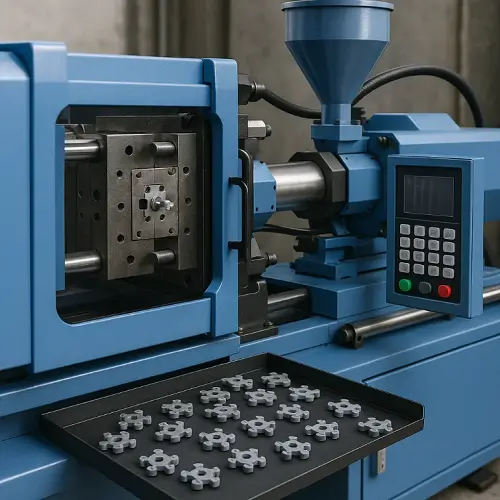
What is micro injection molding?
In engineering practice, we judge whether a part belongs to micro injection molding, not to look at the tonnage of the machine, but to see whether its size, wall thickness, material properties and structure have entered the micro-scale range. Generally speaking, the following types of characteristics are more likely to trigger the micro-injection molding process ……
Products that typically meet one of the following conditions are categorized as being in the micro-injection molding range:
Very light part weight
typically between 0.01-5 g, very little material used in a single mold, and high requirements for injection metering accuracy.
Very thin wall thickness
0.15-0.40 mm is a common range, locally even as low as 0.1 mm.
The thinner the wall thickness, the shorter the mold filling time, and the higher the requirement for injection response speed.
Structures with miniature features
micro gears, tiny snaps, micro runners, thin film areas, small optical structures, etc..
These areas are extremely sensitive to mold temperature, flow and venting conditions.
Tight dimensional tolerances
Functional surfaces generally need to be controlled to ±0.01-0.03 mm.
At such small dimensions, tolerance variations are almost equal to structural variations.
Use of engineering plastics that are sensitive to temperature and residence time
include materials such as LCP, PEEK, PA12, PC, COP/COC.
As parts move into these size ranges, fluctuations common to normal injection molding – mold temperature variations, back pressure fluctuations, excessive melt residence time – are magnified as molding defects. Micro injection molding was created to solve these problems and maintain long-term stability.
Advantages of micro-injection molding
Capable of producing microstructures that are difficult to mold stably with conventional injection molding
Thin-walled, fine features, micro-runners, and compact three-dimensional structures are often short-shot, burnt, and over-shrunk on conventional injection molding equipment. The faster response, smaller barrels, and more precise injection metering of micro-injection molding equipment allow these features to be reliably molded in their entirety. For these structures, “half molding” is not considered a success; only fully stable and repeatable molding makes sense.
Good dimensional consistency for mass production
In micro parts, ± 0.01-0.03 mm size difference is enough to affect the plugging force, sealing performance or optical performance. Micro-injection molding machines are specifically optimized for mold temperature, injection pressure, metering accuracy and screw response, allowing dimensional stability to be maintained over time.
For the medical, connector and optical industries, this is more important than single-shot accuracy.
Reduced material waste, especially for high-performance plastics
Many micro parts use high-value materials such as LCP, PEEK, PC or COC/COP. conventional injection molding machines have large barrels and runners with lots of trapped and cold material. Micro injection molding machines have small barrels and short runners for better material utilization.
More suitable for small products with complex functions
As electronic and medical products continue to be lightweight, some key functions are concentrated in very small plastic structures. The high-precision control of micro-injection molding can reproduce complex details in a limited space, allowing for a more integrated structure and more stable performance.
Typical applications for micro injection molding include
Miniature terminal support structures in electronic connectors
In high-speed connectors and precision electronic assemblies, where the spacing between terminals is often only a few hundred microns, the plastic support structure must maintain sufficient mechanical strength while minimizing size to meet the ever-increasing requirements for overall wiring density. Micro-injection molding stabilizes these elongated, thin-walled geometries and controls the degree of support foot placement to maintain consistent insertion force and alignment accuracy during automated assembly. For applications requiring high temperature resistance or long-term electrical stability, materials such as LCP also exhibit good dimensional stability in micro injection molding.
Medical Microfluidic and Diagnostic Chips in Small Structures
Microfluidic chips, sample reaction chambers, valve seats and liquid guiding structures in medical devices have stringent requirements for geometric accuracy and surface quality. In these devices, the cross-sections of the flow channels are usually very small, and any burrs, short shots or errors that accumulate during the molding process can directly affect the fluid velocity or reaction effect. Micro-injection molding allows the material to fill the runner uniformly and completely and achieve repeatable geometry through precise temperature control and rapid injection. At the same time, since diagnostic devices are often required to be single-use, high efficiency and low material waste become important advantages.
Optical Thin Film Parts, Miniature Lenses and Small Size Light Guide Structures
The optics industry places high demands on the surface quality of molded parts, especially small-volume optics such as indicator lenses, microlenses, and small imaging components. The presence of flow marks, haze, and depressions caused by shrinkage on the surface can affect light transmission and the direction of light propagation. Micro injection molding combined with high polishing precision molds can achieve better optical surfaces in one shot, while avoiding localized stress and deformation in thin-walled areas through reasonable gate design and cooling management, resulting in more consistent optical properties in mass production.
Miniature Gears and Precision Transmission Components
Micro gears, toggles, sliders and other small transmission structures have strict requirements for tooth precision, roundness, runout and dimensional consistency. Ordinary injection molding can result in incomplete tooth shapes or dimensional deviations due to fluctuations in material flow, uneven mold temperatures, or rapid localized cooling, which can affect transmission noise and life. Micro injection molding allows tooth shapes to be clearly reproduced in the cavity through faster molding cycles and more uniform cooling distribution, and maintains stability in tooth pitch, tooth height and engagement angle. For structures requiring low friction and long life, engineering plastics such as POM and PA46 are available as materials.
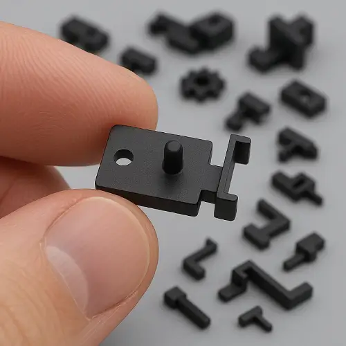
Microholes, Microgrooves and Thin-Wall Structures in Sensor Housings
In pressure, humidity, flow and position sensors, plastic housings often take on the multiple roles of positioning, protection against dust and liquid penetration, and protection of sensitive components. Small holes, microgrooves, channels or extremely thin isolation zones in the housing need to be very dimensionally stable, otherwise assembly, airtightness or sensor response times can be compromised. Micro injection molding provides better mold filling on such products, resulting in clear detail structures and neat boundaries, while reducing burrs and local warping to ensure the reliability of functional areas.
Differences between micro injection molding and conventional injection molding
Although micro-injection molding and conventional injection molding are identical in process, the real difference is not in the process steps, but in the process window and equipment responsiveness. Micro-injection molding has much stricter requirements for metering, mold temperature and injection response, and very often it is not that traditional equipment cannot do it, but that it is difficult to do it consistently over a long period of time.
Equipment level
Micro-injection molding machines use small-capacity, high-response injection units with finer metering and faster injection speeds. The design of the clamping unit is also more suitable for smaller molds to avoid response delays due to increased system inertia.
Mold Level
Miniature molds have finer runners, shallower exhaust slots, and more precise features, requiring more CNC and EDM machining capabilities. Exhaust arrangements are often more numerous and denser to ensure that air can escape in a timely manner.
Process Control Levels
Micro injection molding has a narrower temperature window and faster mold filling. A small temperature drift, a delay of a few milliseconds, can lead to short shots, shrinkage, and scorching. Temperature stability, consistent metering and process monitoring must be maintained over time.
This difference means:
If you put a micro part on a traditional injection molding machine, it can theoretically be made, but long-term consistency and mass production yields are difficult to guarantee.
Process difficulties in micro injection molding
In micro injection molding, many of the problems are not so much that the equipment can’t do it, but rather that all of the influencing factors become more sensitive at the micro-scale. Air venting is a typical example. The smaller the structure, the more limited the space for air to escape, and if the exhaust slots are not deep enough or in the right place, the air can be compressed locally and end up as a burnout or short shot. Small defects that may not be noticeable in conventional injection molding often lead directly to molding failure in microstructures.
The processing window of the material is also a common challenge. Materials like LCP, PA12, and PC flow very quickly in microfluidic channels and thin-walled areas, but are particularly sensitive to temperature fluctuations and residence times. A temperature deviation of just a few degrees and a few extra minutes of material residence time in the barrel can change the flow significantly, resulting in dimensional shifts, uneven color, or loss of strength. This is especially critical for high-volume projects that require long-term stability.
Dimensional control is also much more complex than conventional injection molding. Miniature parts often require microscopic inspection or non-contact measuring equipment, and the measurement method itself can introduce additional errors. To maintain measurement consistency, inspection tools, datums, and sampling frequencies all need to be planned in advance, otherwise the inspection data may “drift” more than the part itself.
Mold processing is also a major difficulty. Miniature mold runners, cavities, exhaust grooves are often only a few hundred microns in depth, the CNC, electrical discharge machining and polishing process stability requirements are very high. Any slight difference in tool wear or discharge conditions may be reflected in the product. The error space of the mold itself is almost equal to the molding error space, so the machining stage must be more tightly controlled.
Common materials for micro injection molding
Depending on the application scenario, common materials include:
LCP (Liquid Crystal Polymer): excellent fluidity, suitable for connectors, thin-walled structures
PEEK: High temperature resistance, high strength, used for medical and industrial functional parts
PA12/PA46: for micro gears or wear-resistant structures
PC, COP/COC: optical parts, transparent windows
POM: low friction characteristics suitable for micro-drive parts.
Specific material selection should consider fluidity, mechanical strength, use of the environment and dimensional stability.
Design Recommendations for Micro Injection Molding (DFM)
In the micro injection molding project, the design often determines whether the later can be successfully mass production. For parts with very small dimensions and sensitive wall thicknesses, we usually look at a few key points first at the drawing stage. The most basic point is to keep the wall thickness as continuous as possible – not that it has to be the same everywhere, but to avoid sudden transitions from thick to thin, a change that can magnify shrinkage, uneven cooling, or filling breaks even more in the microstructure.
If there are very narrow features on the part, we would recommend reserving a transition zone that allows for smooth material entry to avoid the material freezing first at sharp points. Air venting is also an area often overlooked in micro injection molding because the structure is so small that there isn’t much room for air to get out; providing “machinable air venting” for some parts in the design will make the mold a lot easier to work with later in the process.
Material selection is also critical. Materials such as LCP, PEEK, PA12 perform well at high temperatures, but have their own characteristics of dimensional stability. If the part is very sensitive to dimensional deviation, we will recommend a more suitable grade according to the structure. For important dimensions, it is also more effective to plan inspection locations and benchmarks in advance than to try to fix them after molding.
The last point is practical: the location of gates and parting lines should ideally be confirmed with the manufacturer at the design stage. Miniature parts have limited structural space, so if you leave a gate in an unworkable location, it will be difficult to remedy the situation later, no matter how good the equipment is. A little time spent discussing these basics during the design phase can often lead to a much shorter debugging cycle and a much more stable production run.
Why choose Jeek for micro injection molding?
When dealing with micro injection molding projects, we are more concerned with maintaining stability over the long term in volume production than we are with relying solely on the specifications of a particular piece of equipment. For parts with small structures, rapid wall thickness changes, and high material sensitivity, we usually evaluate gating, venting, cooling, and flow paths during the design phase, so that the mold has a controllable process window from the start, rather than relying on late-stage debugging to remedy the situation.
Materials like LCP, PEEK, PA12 are very sensitive to retention time and temperature fluctuations. If the runner or barrel size is not appropriate, deviations can occur even if the equipment itself is fine, so planning is often more important than the molding parameters themselves. We also record the trend of key dimensions at different cycle stages during mold trials to confirm whether the structure will shift over time, and handle cooling or venting ahead of time depending on the situation to make mass production more stable.
If your part involves thin-wall, micro-structure or high precision requirements, it is recommended to send the model along for a look over at an early stage of design. This way we can determine its risk points in microscale molding at the drawing stage and give a more robust tooling and process plan.
If you already have a project in progress, you can also send us the drawing file for more accuracy, so that we can look at the problems that the structure may encounter in microscale molding together, and give a clear and feasible production plan and corresponding cost, contact us.