
Weld lines show up whenever two melt fronts meet colder or slower than they should, something you notice right away on thin-wall or GF-nylon parts. If you’ve worked with thin-wall housings or GF-nylon parts, you’ve probably seen those faint streaks that look cosmetic at first but later turn into the first place to split under stress. Most engineers recognize the look before they even pick up the part.
Across the Weld Lines Injection Molding jobs we’ve handled at Jeek, the pattern rarely changes: weld lines happen where the melt is forced to split, slow down, and meet again after losing energy. You can usually predict their location before the first mold trial—assuming the flow path isn’t fighting the part design.

Understanding How Weld Lines Form in Injection Molding
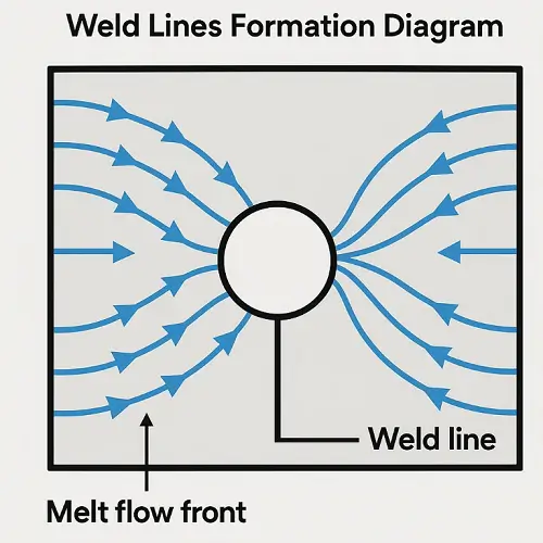
A weld line is one of the more recognizable injection molding defects, created when two melt fronts meet after losing too much heat to fully fuse.A weld line forms when two melt fronts meet colder than they should. Sometimes you can see this happen right on the press—early shots during warm-up usually show sharper weld traces because the mold steel isn’t fully up to temperature yet. It’s one of those small signs molders notice even before the QC team gets involved.
Inside the cavity, each front forms a thin frozen layer as soon as it contacts steel. The two fronts then travel different routes, cool at different rates, and arrive at the convergence point with different molten-core thicknesses. That’s why weld lines consistently show up around holes, rib junctions, shutoffs, and other places where flow has no choice but to divide.
Why Weld Lines Reduce Structural Strength
The strength loss you see at a weld line comes down to the lack of polymer chain entanglement. Cold fronts don’t fuse—they just press together. Anyone who has bent a PC or nylon part along the weld knows how cleanly it can crack even when the rest of the part seems solid.
Glass-filled materials make this even more obvious. The fibers follow the melt direction, so when two fronts meet, each has its own orientation and none cross the seam. In several PA66-GF30 programs we ran, we saw almost identical fracture patterns: the part doesn’t just fail—it opens along the weld line like it was designed that way.
Common Causes of Weld Line Defects
Different process factors can create weld lines, but some patterns are so common that any molding tech will spot them immediately. For example, weld lines are usually more defined early in the shift when mold temperature is lower than steady-state. That alone tells you cooling is beating the melt to the finish line.
Common contributors include:
-
Low melt temperature → Not enough heat to re-melt the opposing skin.
-
Cold molds → Faster freeze-off, thinner molten cores.
-
Slow injection speed → Fronts cool too much on the way.
-
Poor venting → Air cushions between fronts reduce fusion.
-
Gate placement → The geometry forces weld lines into visible or high-stress areas.
At Jeek, we often see cases where adjusting melt temperature helps but doesn’t fully solve the problem. When that happens, the gate layout almost always becomes the real discussion.
Material Behavior and Weld-Line Sensitivity
Different polymers leave their own signature when it comes to weld lines. ABS tends to show visible marks even when strength isn’t heavily affected. PC weld lines can be subtle but mechanically weak—you won’t always see them until the part fails during impact.
With nylon, especially PA66-GF30, weld lines behave differently depending on moisture. You may have noticed this yourself: overdried nylon often produces a sharp, brittle weld line; slightly wetter material softens the appearance but sometimes loses strength faster. Even with PP, which is usually forgiving, thin sections can still create very visible weld lines when the fronts cool too much.
In our shop, we’ve seen GF-nylon weld-line sensitivity show up the most consistently on long-flow parts or parts with asymmetric rib structures.
Improving Weld Line Quality in Injection Molding
Improving weld-line performance usually starts by restoring melt-front energy. You’ve probably watched weld lines soften immediately after raising the mold temperature a few degrees—it’s a small adjustment, but it slows freeze-off enough to help the fronts merge with more usable heat.
Some of the most reliable improvements include:
-
Higher melt temperature (within spec)
-
Higher mold temperature (slower freeze-off)
-
Faster injection speed (hotter fronts on arrival)
-
Cleaning or deepening vents (letting fronts meet cleanly)
On several housings we molded at Jeek, weld lines didn’t improve until the vents were cleaned. Once venting was restored, the weld trace softened so noticeably that the operator pointed it out before we even checked dimensions.
And then there’s gating. A slight shift in gate angle or gate size can completely redirect where the weld forms. When weld lines barely respond to temperature or speed tweaks, gate layout is almost always the missing link.
Weld Lines vs. Knit Lines
A weld line forms when fronts meet cold; a knit line forms when they meet warm enough to fuse but still leave a visual trace. If you’ve flexed parts during sampling and seen the mark stay intact, that’s a knit line. If it opens instantly, you’re dealing with a weld line.
This difference matters because one is mostly cosmetic and the other affects structural approval.
Design Considerations to Reduce Weld Line Defects
Most weld-line issues are easier to prevent at the CAD stage than at the press. Engineers who’ve reviewed enough flow reports know how small tweaks—like moving a rib intersection or softening a sharp corner—can shift a weld line by several millimeters.
A well-directed gate helps even more. When the flow comes toward the weld-sensitive region instead of pulling away from it, the fronts meet hotter and fuse better. We’ve recommended minor gate reorientations on multiple customer tools, and in many cases the weld-line concern disappeared during T1.
Simulation and Flow Analysis for Predicting Weld Lines
Simulation tools make predicting weld lines far easier than guessing from geometry alone. They show exactly where fronts split, how fast each cools, and how fibers orient at the weld region. If you’ve compared simulation output to molded samples, you’ve probably seen how close the match is—flow fronts rarely lie.
On GF materials, simulation becomes almost mandatory because fiber angles heavily influence weld-line strength.
Conclusion
Weld lines aren’t going away in injection molding, but they can be pushed out of the areas where they cause real trouble. When the melt front arrives hot, the mold breathes properly, and the gate drives flow the right way, weld-line severity becomes predictable instead of frustrating.
At Jeek, we’ve worked through weld-line challenges on housings, structural components, and long-flow GF-nylon parts. Almost every improvement came from balancing melt-front energy, venting, and gate direction—not from chasing extreme parameter changes. Once those fundamentals line up, weld lines behave consistently from run to run, which is ultimately what keeps production stable.