
Injection molding involves constant interaction between resin behavior, steel temperature, flow resistance, and cooling balance. Even a well-designed mold can produce parts that look slightly different from run to run—changes in gloss, small surface marks, or subtle dimensional drift. These signs usually reflect what happened inside the cavity: how the melt advanced, where it slowed down, and how the part cooled before ejection.
For engineers and production teams, reading these signals is essential for maintaining stable, repeatable quality.

What Is Injection Molding Defects
Injection molding defects are surface or structural variations that occur when melt flow, cooling behavior, venting, or material condition moves outside the intended processing window. Some defects are cosmetic—flow lines, splay, blush marks. Others point to underlying issues such as gas entrapment, uneven shrink, shear overheating, or resin degradation.
Each defect leaves its own visual pattern. By linking that pattern to flow behavior, packing performance, heat transfer, or mold condition, engineers can identify the root cause and determine whether the solution lies in processing adjustments, tooling changes, or material handling.
Below are the defects most frequently observed during sampling and early production.
Flow Lines
Flow lines appear as wavy streaks that follow the movement of the melt. They typically show up when the material cools faster than it should, when injection speed is lower than the geometry demands, or when the melt hesitates around thickness changes. The pattern is mostly cosmetic, but it signals that the flow or temperature balance was not steady during filling.

A more uniform surface can often be achieved by raising melt or mold temperature, increasing injection speed, or smoothing abrupt transitions so the melt front keeps its momentum as it advances.
Sink Marks
Sink marks occur when the surface freezes but the interior continues to shrink. Ribs, bosses, and thick pads are the most common areas where the surface collapses inward. These marks usually point to insufficient packing, slow cooling inside the thick section, or excessive mass in the design.

Reducing local wall thickness, improving cooling in deep sections, or applying stronger packing pressure helps support the surface while the core material finishes shrinking.
Knit Lines / Weld Lines
Knit lines or weld lines form where two melt fronts meet after losing more heat than the design or process intended. They frequently show up around holes, ribs, or any feature that splits and then rejoins flow. The surface may appear slightly different in gloss or texture, and depending on the resin and fiber content, the region can also be mechanically weaker than the surrounding material.

Improving the fusion at these meeting points typically involves raising melt temperature, ensuring pressure is available when the fronts converge, or adjusting gate location and flow direction so the melt arrives hotter and more active. When the melt fronts meet with enough temperature and energy, the surface blends more cleanly and the structural drop at the weld is minimized.
Short Shot
A short shot happens when the melt cannot reach the end of the cavity. Restricted flow, frozen gates, limited pressure, or trapped air can stop the melt front prematurely. Thin-wall parts and long flow paths tend to exaggerate this issue.

More complete filling is usually achieved by increasing injection pressure, improving venting, adjusting gate or runner size, or stabilizing melt temperature to keep the material moving.
Voids
Voids appear as internal hollow pockets when the interior cools faster than the surface can support. They usually develop in thick sections or isolated masses where cooling is uneven. Although hidden, they can reduce load-bearing capability.
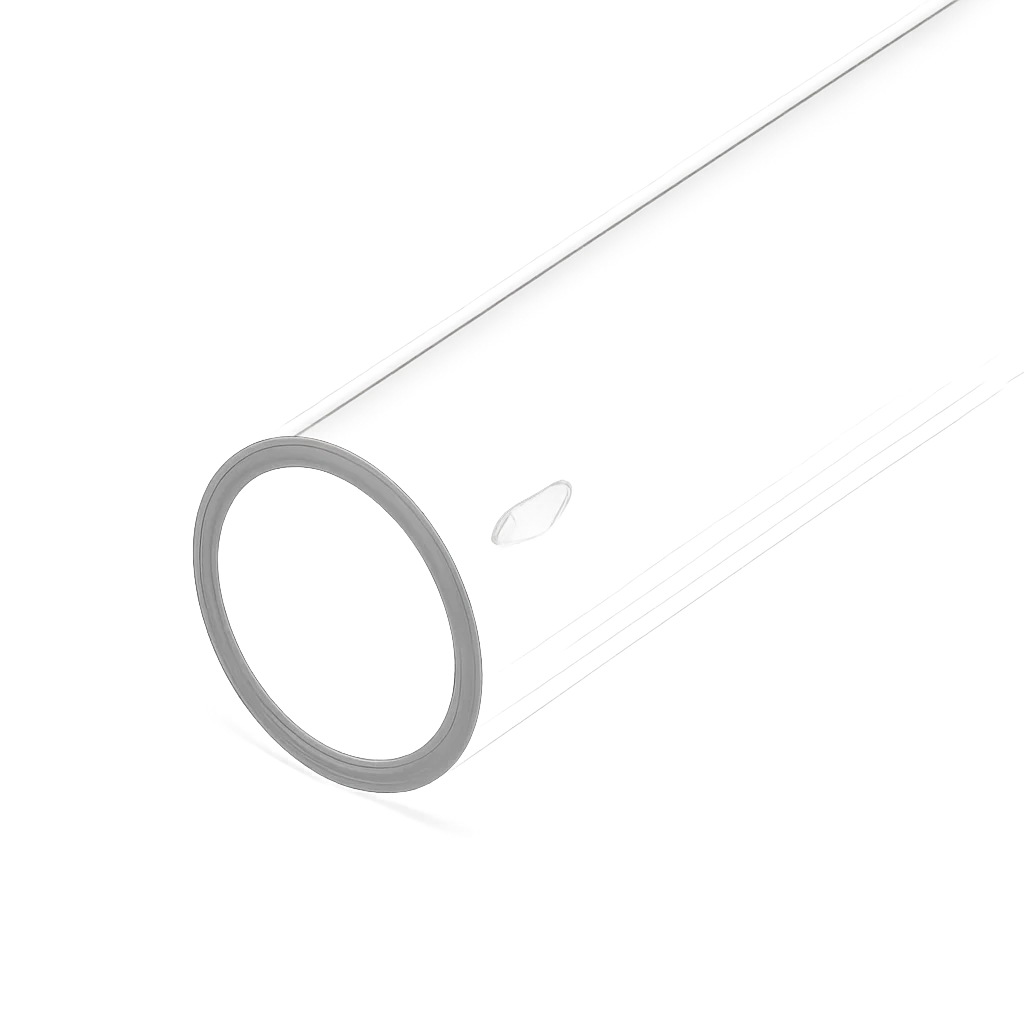
Balancing wall thickness, strengthening packing in high-mass regions, and improving cooling efficiency reduces the internal shrink behavior that causes voids.
Bubbles
Bubbles appear when moisture or trapped air enters the melt. Materials such as nylon and PC show bubbles quickly if drying is inconsistent, and the melt front can trap air if venting is limited.

Consistent drying, proper purging, and improving venting paths help remove air and moisture before they enter the melt stream, reducing the chance of visible bubbles.
Flash
Flash forms when molten plastic escapes through parting lines or shutoff areas that are unable to hold pressure. Worn steel, high packing force, or insufficient clamping are common contributors.

Restoring shutoff surfaces, moderating packing pressure, or increasing clamp tonnage usually keeps the melt contained within the cavity.
Jetting
Jetting shows up when the melt leaves the gate with more velocity than the cavity can guide. Instead of flowing against the steel, the stream lifts off, coils in mid-air, and freezes the moment it hits a colder surface. That early rope becomes the first layer of the part, and once it hardens, no amount of packing blends it back into the flow. You’ll see this most in cold-gate startups, narrow gates pointed into open space, or thin-wall parts where the melt doesn’t have enough time to wet the wall before accelerating.

Once the rope forms, flow behavior shifts. Packing pressure deflects around the hardened strand, gloss becomes uneven, and on glass-filled materials the fibers lock into the shape of the early jet. Fixing it usually means giving the melt something to follow—warmer steel near the gate, a gentler initial velocity, or a gate angle that aims the melt along a surface instead of letting it free-shoot across empty space.
Burn Marks
Burn marks appear exactly where trapped air compresses faster than it can escape. At the end of fill—sharp corners, deep pockets, long ribs—the melt arrives quickly, the air has nowhere to go, and temperature spikes high enough to scorch the surface. On materials like ABS, PC, or POM, that discoloration becomes instantly obvious because the polymer degrades faster under localized heat than the rest of the flow path.

When burn marks show up in the same spot shot after shot, it almost always traces back to vent depth, vent contamination, or a small mismatch that blocks air movement. Adjusting injection speed or melt temperature may soften the color, but lasting improvement comes from restoring venting or reducing the pressure spike that occurs in the final few millimeters of flow.
Splay Marks
Splay marks develop when volatiles—usually moisture or degraded resin—flash to steam and erupt onto the surface as the melt advances. These fine, silver-white streaks follow the flow direction and are most dramatic on glossy or transparent parts. Hygroscopic resins like PC, PA, and ABS show this instantly when drying slips even slightly, and the streaking becomes worse the longer the residence time climbs.

When moisture is ruled out, shear becomes the next suspect. High screw RPM, excessive back pressure, worn barrels, small gates, or restrictive runners can overheat the melt and release chemical volatiles. A resin that has been over-worked won’t hide it—those vaporized pockets burst at the surface the moment the melt front hits colder steel. Improving drying discipline, reducing shear sources, and stabilizing mold temperature typically bring splay under control.
Warping
Warping happens when different regions of the part cool at different rates, pulling the geometry out of plane as the plastic solidifies. Long, thin panels, ribs with heavy mass beneath them, and materials with strong flow orientation all exaggerate this effect. The part usually looks perfect while still in the mold, but once the clamps open and the stress is released, the imbala nce shows itself.

Solving warp rarely comes from parameter adjustments alone. The real gains come from evening out the cooling path: better water channel distribution, correcting temperature gradients across cores and cavities, or redesigning walls so shrinkage occurs more uniformly. Packing behavior matters too—if one zone freezes early, the remaining areas continue shrinking without support and the part moves toward the hotter or thicker region.
Gate Blush
Gate blush forms when the melt experiences a high-shear shock as it exits the gate and hits cooler cavity steel too abruptly. The result is a cloudy, stress-whitened halo around the gate—more visible on ABS, PC, or other resins sensitive to surface stress. Blush doesn’t appear because the surface is damaged; it appears because the melt freezes before it has a chance to relax and smooth out.
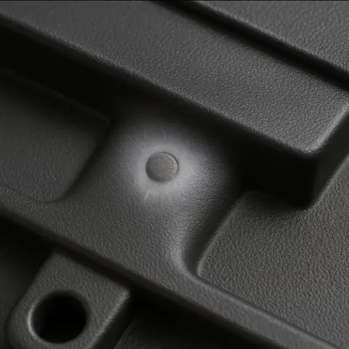
Reducing blush usually means easing how the melt enters the cavity. A larger gate, a small radius, a smoother gate land, or a slightly warmer gate region helps the melt wet the surface instead of streaking across it. When blush remains even after fill adjustments, the gate geometry or direction is almost always the underlying cause.
Black Specks
Black specks are carbonized fragments—burnt resin, degraded material, or contamination—breaking loose from the barrel, screw, or hot runner. Light-colored parts make them obvious, but the root cause is almost always upstream. Long residence time, overheated zones, dead spots in the screw, or contamination left inside dryers and loaders feed these particles back into the melt.
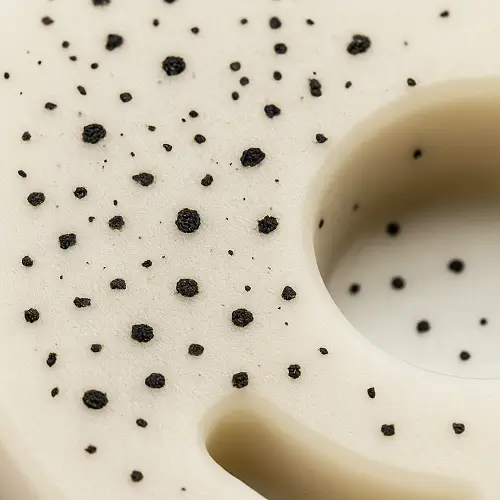
Prevention isn’t about the cavity—it’s about the plasticizing system. Purging sequences, barrel temperature control, screw maintenance, and proper material handling eliminate most sources of specks. If the defect returns at the same frequency, check for worn screws, damaged check rings, or hot-runner stagnation that can accumulate char.
Ejector Marks
Ejector marks appear when a part grips the core harder than the pins can push cleanly. Uneven cooling, minimal draft, or soft resin temperature at ejection allows the pin face to leave a circular or polished imprint. On textured parts, the mark becomes even more visible because it disrupts the pattern in a perfect circle.
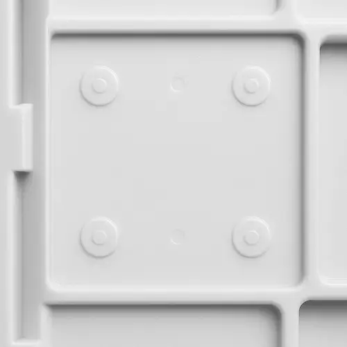
Reducing ejector marks depends on lowering grip or distributing force. Cooler, more balanced steel temperatures, smoother pin surfaces, slowed ejection speed, or relocating pins to more forgiving areas all reduce the imprint. When the same pin mark keeps returning, the issue usually lies in that pin’s surface condition or localized shrink that causes the part to stick.
Conclusion
The injection-molded part is a blueprint of the events that occurred inside the cavity. Every defect pattern—from subtle surface variations to obvious structural flaws—precisely records how the melt advanced, where the pressure was maintained, and how heat was transferred.
By mastering the interpretation of these “signals,” engineers can achieve predictive troubleshooting, transforming complex processing challenges into stable, repeatable production cycles.
At Jeek, this in-depth evaluation of defect patterns is central to our daily production and new mold validation process.
We offer more than just manufacturing; we provide expert injection molding engineering insight.
If you are currently facing challenges such as:
-
New mold optimization and stabilization
-
Troubleshooting persistent production issues
-
Professional review of part geometry or gating design
Ready to optimize your production or get a quote?
[Click Here to Get a Quote/Contact Us Today]
Feel free to share your CAD files or drawings with us. Our engineers will review your design and offer practical, production-ready guidance to ensure your product quality and efficiency are maximized.