
injection molding problems get treated as separate issues when they first show up on parts. One housing comes out with burn marks near the end of fill. Another part starts short-shooting in a thin section. A different tool flashes at the parting line after the process is pushed harder. On the surface, those look like different defects. In real mold development, they often point back to the same basic question: can the trapped air and gas get out of the mold fast enough and in the right place?
That is why venting in injection molding matters much more than many teams expect. Venting is easy to ignore when the mold is still on the screen, because nothing in CAD looks like “air trouble.” But once the tool is running, the air inside the cavity becomes part of the process whether the design planned for it or not. If the venting path is weak, blocked, too small, or simply placed in the wrong area, the result shows up on the part. Sometimes it shows up as gas burning. Sometimes it stops the melt front before the cavity is full. Sometimes it forces the team to push the process harder until flash starts appearing somewhere else.
That is why this topic is worth treating as a mold design issue, not just a machine setting issue. Poor vent design can make a good part look unstable. Good injection mold venting can make the same tool much easier to run, easier to troubleshoot, and easier to move toward production.
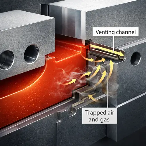
What Is Venting in Injection Molding?
Venting in injection molding is the controlled path that allows air and gas to escape from the cavity while molten plastic is filling the mold. Without that escape path, the incoming material has to fight trapped air as it moves through the part. Once that happens, pressure builds where it should not, the melt front becomes less stable, and the tool starts showing problems that often look unrelated at first.
In practical terms, injection mold venting is not a decorative detail. It is part of how the cavity works. Every shot begins with air already inside the mold. When the resin enters, that air has to go somewhere. If it is pushed out cleanly, filling is smoother and part quality is easier to control. If it gets trapped, the air compresses, heats up, and resists the incoming material. That is when burn marks, short shots, weak filling at the end of the flow path, or unstable cosmetic results begin showing up.
This is also why venting should not be confused with simply “opening the mold a little” or letting the parting line leak. Real mold vent design is controlled. The goal is to let gas out without letting plastic escape in a way that turns into flash. That balance is where good venting design becomes a mold engineering decision, not just a process reaction.
Why Venting Problems Are Easy to Misread
Venting problems are easy to misread because they rarely announce themselves with a neat label. A part may show a blackened area near the last fill point and look like a temperature problem. Another may come out short in a rib or thin wall and look like an injection pressure issue. A third may start flashing after the settings are pushed harder to get the cavity full. The visible result changes, but the root cause may still be poor venting.
That is why these issues often waste time during trials. Teams adjust melt temperature, injection speed, hold pressure, clamp force, or mold temperature and sometimes see partial improvement. Then the problem returns under slightly different conditions. The process seems unstable, but the real reason is that the cavity still does not have a clean way to release trapped gas.
This is one of the easiest traps in mold trials. A process problem and a venting problem can look similar at the machine, especially in the first rounds of sampling. The difference is that a true venting problem usually keeps coming back in the same area, especially near the end of fill, deep ribs, shut-off regions, complex corners, or places where the melt front is expected to trap air.
Another clue is how the defect changes when the settings are pushed. If a weak fill area turns into a burn mark after speed or pressure is increased, or if a short-shot region fills only after the machine is driven harder and then flash shows up elsewhere, the tool is often telling the same story in different ways. The symptom changed, but the trapped-gas problem stayed in the same place.
How Poor Venting Causes Burn Marks in Injection Molding
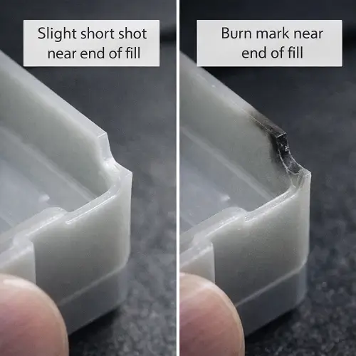
Burn marks are one of the clearest warning signs that the mold is not releasing trapped gas well enough. They usually show up where air is compressed into a tight area and has no clean way out. The compressed gas heats up quickly, and that local heat can scorch the resin or leave dark streaks, blackened edges, or burnt-looking spots on the finished part.
That is why burn marks in injection molding often appear near the end of fill rather than near the gate. The material itself may still be flowing correctly through most of the cavity. The problem starts when the last pocket of air gets trapped and squeezed with nowhere to escape. At that point, the resin is not only filling the part. It is also compressing hot gas into a very small space.
This is where mold vent design becomes much more important than simply lowering speed and hoping the problem fades. Slowing the process may reduce the symptom in some cases, but it does not change the fact that the gas still needs an escape path. If the trapped region is built into the geometry, the burn mark usually keeps returning until the venting strategy is improved or the flow path is changed enough to stop trapping air in that location.
A practical way to read burn marks is to ask where they appear and how repeatable they are. If the mark keeps returning at the same last-fill location, especially in a closed corner, deep rib end, or shut-off-sensitive area, venting becomes a much stronger suspect than a random temperature fluctuation. A true overheat issue can move around more easily. A trapped-gas burn usually stays loyal to the same geometry.
Can Poor Venting Cause Short Shots in Injection Molding?
Yes, and it happens more often than many people expect.
A short shot does not always mean the machine could not push enough material. In many cases, the melt front reaches a point where trapped air begins resisting the fill. The machine is still injecting, but the cavity is no longer accepting the material smoothly because the air in front of the melt has nowhere to go. Instead of filling the end of the part, the resin stalls and leaves an incomplete section.
This is one reason short shots are common in thin walls, deep ribs, end-of-flow features, long flow length areas, and cosmetic covers with restricted escape paths. If the geometry already makes filling difficult, poor venting makes the problem much worse. A part may look close to full in one shot and then miss the same end feature in the next when the process window shifts only slightly.
That kind of repeat behavior usually tells an important story. If the same section keeps failing near the same end point, and especially if the defect gets worse when the resin front reaches a trapped pocket, venting becomes a much more likely cause than a random machine problem. At that point, increasing pressure may help temporarily, but it often does so by forcing the process closer to flash or other instability.
Short shots linked to venting also tend to behave differently from short shots caused mainly by weak gate design or extreme wall thickness changes. A gate-related fill problem often shows itself earlier in the flow path or across a broader region. A venting-driven short shot is more likely to show a stubborn failure at the last place the cavity wants to fill, especially where the air has nowhere easy to escape.
Why Venting Problems Can Increase Flash in Injection Molding
Flash and poor venting can seem like opposites at first. One problem looks like the cavity is too tight for air to escape. The other looks like plastic is escaping too easily. In real tooling, those two problems can be closely connected.
When a mold does not vent well, the first reaction during trials is often to push the process harder. Higher fill pressure, more aggressive speed, or stronger packing may help force the resin farther into the cavity. That may reduce short shots or improve weak filling in the moment, but it also puts more stress on shut-off areas and parting surfaces. If the steel condition is already sensitive, flash can start appearing because the tool is now being pushed harder than it should be just to compensate for trapped gas.
There is another side to this too. A vent that is too open, too deep, poorly controlled, or worn over time can also become a flash path. That is why venting design is always a balance. A mold needs enough venting to release gas cleanly, but not so much freedom that molten plastic escapes and creates a new defect.
This is one of the reasons venting should not be treated as a simple “more is better” feature. Good venting in injection molding means controlled gas release. Bad venting can cause burns, short shots, unstable fill, and then push the team toward machine settings that bring flash into the picture as well.
In actual trials, this sequence is common enough to be worth watching for. A part starts with weak filling at the end of the cavity. Settings get pushed. The cavity fills better. Then a shut-off edge or parting line begins to flash. If that sequence happens, the flash may not be the first problem at all. It may be the result of trying to solve an under-vented cavity with extra machine force.
Where Injection Molds Usually Need Venting
The places that need venting most are usually the same places where air gets trapped most easily. End-of-fill areas are the most obvious example, because that is where the air is being pushed last. But they are far from the only places that matter.
Deep ribs, narrow channels, shut-off regions, insert interfaces, thin-wall ends, and corners where the flow front wraps around geometry can all become gas traps. Side actions and complex split lines can make those areas even harder to vent if the design only focuses on steel shape and not on gas movement. Features that look simple from a product standpoint can become difficult from a venting standpoint once the mold actually begins to fill.
That is why good injection mold venting starts with understanding where air will want to stay. A mold does not need vents everywhere in the same way. It needs venting where trapped gas is most likely to fight the incoming melt. That is also why vent depth, vent width, and vent location should be treated as part of filling behavior, not as an afterthought added after the first trial already shows trouble.
It also helps to think in terms of “last escape paths.” If the flow front wraps around a boss, closes around a core, or pushes into a long ribbed section, air can end up trapped even when the overall cavity shape looks straightforward. In those cases, the vent requirement is created by the flow sequence, not just by the outer shape of the part.
What Bad Venting Looks Like During Mold Trials
Bad venting often announces itself through unstable symptoms rather than one perfect diagnostic sign. The same part may burn in one area during one trial, then start filling weakly there in the next after the process is adjusted. Another part may need more and more push just to fill the last section, and then flash appears at the parting line or shut-off edge once the settings are raised.
That pattern matters. When the same region keeps creating trouble under different machine settings, the mold is usually telling you something. A persistent end-of-fill burn, a thin section that refuses to fill cleanly, a rib that alternates between short shot and weak pack, or a cosmetic face that becomes unstable when the process is pushed harder all point toward venting as a serious suspect.
This is where trial experience matters. A lot of teams lose time because each symptom gets treated separately. The burn mark gets one explanation. The short shot gets another. The flash gets blamed on clamp or fit. In some tools, all three are really part of the same story. The cavity is not breathing well, so the process is being forced to do work that the mold should be helping with.
Another real sign is inconsistency near the same region even when the rest of the part looks stable. The gate area may look fine, the main wall may pack well, and most dimensions may seem close, but one end feature keeps drifting between weak fill, dark marks, or slight flash-related instability. That kind of local behavior is often much more useful than a general “the whole process feels unstable” comment.
Process Problem or Venting Problem? How to Tell the Difference
This is one of the most useful questions in real projects. If the issue is truly process-driven, adjustments at the machine should improve it in a stable and repeatable way. If the issue is strongly tied to poor venting, the defect usually keeps coming back in the same location or returns when the process window moves only slightly.
A process issue often changes with machine settings in a more predictable way. A venting issue tends to stay attached to a certain area of the part or a certain stage of the fill. It may get a little better when speed is reduced, or when pressure is increased, but the root behavior does not disappear. The defect simply changes form. The same trapped-gas region that caused a burn mark may later show a short shot once the settings are softened. The same under-vented area that needed more push to fill may later bring flash somewhere else once the machine is forced harder.
That is why troubleshooting has to look at location and pattern, not just symptom. If the issue stays married to the same geometry, the same end-of-fill zone, or the same shut-off region, venting deserves a much closer look. Machine settings may still help, but they are probably not the whole answer.
A useful shop-floor rule is this: if the defect moves easily when the process changes, start with process. If the defect keeps returning in the same exact place and only changes its form when the process changes, start suspecting the mold. That is not a perfect rule, but it is often a better starting point than treating every visible defect as a separate issue.
What to Review Before Cutting Steel
The best time to think about venting is before the mold is cut, not after the first trial has already exposed the weak points.
That review starts with flow path and geometry. Long flow lengths, thin sections, deep ribs, closed corners, and end-of-fill features should all raise the same question: where will the trapped air go? If the answer is vague, the mold is already carrying risk. Complex shut-offs, inserts, and side-action regions should also be reviewed carefully, because they often create places where air is easy to trap and hard to release.
Appearance requirements matter too. Cosmetic housings, glossy surfaces, and visible outer shells are less forgiving when venting is weak. A small burn mark, gas blush, or unstable surface near the end of fill may be unacceptable even if the part technically forms. In those cases, venting should be treated as part of cosmetic planning, not only as a technical mold detail.
This is exactly where DFM review adds value. A tool may be buildable on paper and still be vulnerable in production because the gas path was never truly considered. Good venting design is one of the quiet differences between a mold that merely runs and a mold that runs cleanly.
It is also worth reviewing how the chosen gate location affects trapped-air behavior. A gate that looks fine for flow length may still create a last-fill pocket in the worst possible place for venting. The venting strategy should be reviewed together with gate direction, shut-off condition, and end-of-fill geometry, not as a separate check added at the very end.
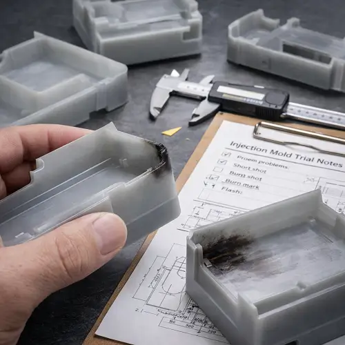
A Realistic DFM Scenario: Burn Marks, Short Shots, and the Same Root Cause
A thin-wall housing with a long flow path can be a good example. The first trial may show a slight short shot near the far end of the part. The natural reaction is to push the process harder. The cavity fills better, but now a dark burn starts appearing at nearly the same location. The next adjustment lowers the severity of the burn, but the cosmetic face becomes less stable and another edge starts flirting with flash because the process is being driven too aggressively just to keep the part full.
At that point, it is easy to think the tool has three separate problems. In reality, it may have one main problem: the gas at the end of fill is not escaping well enough. The short shot, the burn mark, and the growing flash risk all came from trying to make one under-vented region behave through machine settings alone.
This is the kind of pattern that shows up in real trials more often than people expect. A team may spend several runs chasing pressure, speed, and packing because each change appears to solve one symptom for a moment. But when the same end feature keeps misbehaving and the symptom only changes form, the cavity is often asking for a better vent path rather than another parameter adjustment.
That is why this kind of issue is so important to catch early. It saves time, but it also saves the team from chasing the wrong cause. Once the venting path is improved, the process often becomes easier to control because the machine no longer has to fight the trapped gas on every shot.
Conclusion
Injection molding venting is easy to overlook when a project is still in design, but poor vent design can quietly drive some of the most frustrating problems in mold trials and production. Burn marks, short shots, unstable filling, and even flash risk do not always start as separate defects. In many tools, they are different ways the mold is telling you the cavity is not releasing trapped gas properly.
That is why venting in injection molding should be treated as a mold design decision, not just a process adjustment topic. The right venting strategy helps the cavity fill more cleanly, reduces gas-related defects, and makes the process easier to stabilize. The wrong venting strategy forces the machine to work around a mold limitation, and that is when one visible problem often turns into three.
If a part already includes long flow paths, thin walls, deep ribs, cosmetic surfaces, or shut-off-sensitive geometry, venting deserves attention before the tool reaches trial. Send your drawings to JeekMould for a DFM review and quote if the goal is to reduce gas-trap risk, improve mold stability, and move the project toward a cleaner production result.
FAQ
What is venting in injection molding?
Venting in injection molding is the controlled path that allows trapped air and gas to escape from the cavity while the molten plastic fills the mold.
How does poor venting cause burn marks?
Poor venting traps air in the cavity. When that gas is compressed and heated during filling, it can scorch the resin and leave burn marks near the end of fill.
Can poor venting cause short shots?
Yes. If trapped air cannot escape, it can resist the melt front and stop the cavity from filling completely, especially in thin sections and end-of-flow areas.
Does venting affect flash in injection molding?
Yes. Weak venting can force the process to run harder just to fill the part, which can increase flash risk elsewhere. Poorly controlled vent areas can also become direct flash paths.
When is venting a mold design issue instead of a process issue?
When the same area keeps showing burn marks, short shots, or unstable fill under different machine settings, and especially when the problem stays tied to the same geometry, it is often more than a simple process issue.