
An injection molding machine does more than push melted plastic into a mold. The machine has to dry or receive the resin, melt the material, prepare a consistent shot, inject plastic under pressure, hold the mold closed, control temperature and timing, open the mold, eject the part, and repeat the cycle with stable results.
For customers and product designers, the machine may look like one large piece of equipment. For a molder, the machine is a group of working systems. The injection unit prepares and delivers the plastic. The clamping unit holds the mold. The screw and barrel control melt quality. The nozzle connects the machine to the mold. The control system manages pressure, speed, temperature, timing, and movement.
These machine components matter because they affect the final plastic part. A well-built mold still needs the right machine behind it. If the shot capacity is too small, the part may not fill consistently. If clamping force is too low, flash may appear. If the screw and barrel do not prepare the resin correctly, the part may show bubbles, streaks, black specks, or unstable weight.
This article breaks down the main injection molding machine components and explains what each part does in practical manufacturing language.
What Are the Main Injection Molding Machine Components?
The main injection molding machine components include the injection unit, hopper, screw, barrel, heater bands, check ring, nozzle, clamping unit, fixed platen, moving platen, tie bars, mold mounting area, ejector system, hydraulic or electric drive system, control system, safety guards, and cooling or temperature control connections.
The injection unit melts and injects plastic. The clamping unit holds the mold closed during filling and packing. The screw and barrel prepare the melt. The nozzle transfers molten plastic into the mold. The platens hold the mold. The tie bars guide platen movement and support clamping force. The control system manages pressure, speed, temperature, position, and cycle timing.
A stable injection molding process depends on all of these systems working together, not on one component alone.
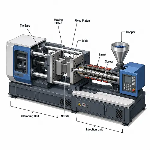
Injection Molding Machine Diagram: How the Main Systems Work Together
A typical injection molding machine has two major sides: the injection side and the clamping side.
The injection side includes the hopper, barrel, screw, heater bands, check ring, and nozzle. Plastic pellets enter from the hopper, melt inside the heated barrel, and are pushed forward by the screw. The nozzle then delivers molten plastic into the mold.
The clamping side holds the mold. The fixed platen supports the stationary mold half, while the moving platen opens and closes the other mold half. The clamping unit keeps the mold closed during injection and packing. After cooling, the mold opens and the ejector system pushes the part out.
| Machine Area | Main Function |
|---|---|
| Injection unit | Melts and injects plastic into the mold |
| Hopper | Feeds plastic pellets into the barrel |
| Screw and barrel | Melt, mix, meter, and prepare the resin |
| Nozzle | Transfers molten plastic into the mold sprue or hot runner |
| Clamping unit | Holds the mold closed during injection and packing |
| Fixed and moving platens | Support and move the mold halves |
| Tie bars | Guide platen movement and support clamp structure |
| Ejector system | Pushes molded parts out after cooling |
| Control system | Controls pressure, speed, temperature, timing, and position |
A mold may look small from the outside, but the machine still has to match its clamp force, platen size, shot size, opening stroke, ejector stroke, and process requirements.
Injection Unit Components
The injection unit prepares the plastic material and pushes the melt into the mold. This system has a direct effect on melt quality, shot consistency, injection pressure, surface finish, and part weight.
Hopper
The hopper stores plastic pellets before they enter the barrel. It looks simple, but stable feeding begins here. If pellets bridge, feed unevenly, contain moisture, or carry contamination, the molded part may show defects even when the mold and machine settings look correct.
For hygroscopic materials such as nylon, PC, PBT, PET, and some TPU grades, material drying before feeding is critical. Wet resin can cause bubbles, splay, silver streaks, weak mechanical properties, and poor surface finish.
Barrel
The barrel holds the screw and provides a heated path for the resin. Heater bands around the barrel help bring plastic into the correct processing range. The barrel temperature profile must match the resin.
If the barrel temperature is too low, material may not melt or flow properly. If temperature is too high, the resin may degrade, discolor, release gas, or form black specks. Barrel condition also matters. A worn barrel can reduce plasticizing consistency and affect shot stability.
Screw
The screw rotates inside the barrel and moves resin from the feed zone toward the nozzle. A typical screw has feed, compression, and metering sections. The feed section moves pellets forward. The compression section melts and compresses the resin. The metering section helps prepare a more uniform melt before injection.
The screw affects melt quality, color mixing, fiber distribution, shot consistency, and material stability. Screw speed and back pressure also influence how well the material is mixed and how much shear heat is added.
A worn screw can create unstable shot size, poor melt quality, color streaks, black specks, or inconsistent part weight. Filled materials such as glass-filled nylon or mineral-filled resin can accelerate screw and barrel wear.
Heater Bands
Heater bands control the heat added along the barrel. They do not work alone, because screw rotation also creates shear heat. The machine must balance external heat and shear heat so the resin reaches the correct melt condition.
Poor heater control can cause unmelted pellets, material degradation, unstable viscosity, or surface defects. For engineering plastics and heat-sensitive materials, temperature control is especially important.
Check Ring and Screw Tip
The check ring, also called a non-return valve, sits near the front of the screw. Its job is to stop molten plastic from flowing backward during injection.
During screw recovery, molten plastic builds in front of the screw. During injection, the screw moves forward and the check ring closes so the melt is pushed through the nozzle instead of leaking backward over the screw.
A worn or leaking check ring can cause unstable part weight, drifting cushion position, poor packing, short shots, sink marks, or dimensional variation. When part weight changes randomly from shot to shot, the check ring is one of the machine components worth checking.
Nozzle
The nozzle connects the injection unit to the mold. It transfers molten plastic from the barrel into the mold sprue bushing or hot runner system.
Nozzle contact must be stable. If the nozzle does not seat correctly against the sprue bushing, material can leak, drool, freeze, or create process variation. Nozzle temperature also matters. If the nozzle is too cold, material may freeze and restrict flow. If it is too hot, resin may drool or degrade.
For some materials and mold designs, nozzle type also matters. Open nozzles are common. Shutoff nozzles may be used when drool control is important. The nozzle radius and sprue bushing radius must match properly to prevent leakage and support smooth material transfer.
Clamping Unit Components
The clamping unit opens, closes, and holds the mold during the injection molding cycle. During filling and packing, molten plastic creates pressure inside the cavity. That pressure tries to open the mold. The clamping unit resists that force.
Fixed Platen
The fixed platen holds the stationary side of the mold. The injection unit pushes material through the nozzle into the mold on this side. The fixed platen must support the mold securely and keep the nozzle and sprue area aligned.
Moving Platen
The moving platen carries the moving half of the mold. It travels forward to close the mold and backward to open the mold after cooling. The moving platen must move smoothly and stay aligned during repeated cycles.
Tie Bars
Tie bars guide the moving platen and help carry clamping load. The space between tie bars limits the mold size that can physically fit into the machine. This is why machine selection is not only about tonnage. A mold may require moderate clamp force but still need a larger press because of mold base width or height.
Clamp Mechanism
The clamp mechanism provides the force needed to keep the mold closed. Some machines use toggle clamping. Others use hydraulic clamping. Electric and hybrid machines use different drive systems depending on the machine design.
If clamp force is too low, the mold may open slightly during filling or packing, which can cause flash at the parting line, vents, inserts, or shutoff areas. Too much clamping force is also not always ideal because it can reduce venting effectiveness, increase energy use, and add unnecessary stress to the mold.
Mold Height and Opening Stroke
The machine must fit the mold thickness and provide enough opening stroke for part removal. A mold that is too thick, too tall, or requires a long opening stroke may not run properly on a smaller press.
For deep parts, large housings, or molds with complex ejection, opening stroke and daylight matter as much as clamp tonnage.
Toggle, Hydraulic, Electric, and Hybrid Systems
Injection molding machines can use different drive and clamping systems. Each type has its own strengths.
Hydraulic Machines
Hydraulic machines use hydraulic pressure to drive injection, clamping, and other movements. They are common, powerful, and suitable for many general injection molding applications.
Electric Machines
Electric machines use servo motors for major movements. They can provide precise control, lower energy use, cleaner operation, and fast response. Electric machines are often used for precision molding, medical parts, small parts, or clean production environments.
Hybrid Machines
Hybrid machines combine hydraulic and electric systems. They may use electric drives for precision movement and hydraulic power for high-force operations.
The machine type can affect energy use, repeatability, maintenance, cycle speed, and process control. For customers, the important point is not the machine label alone, but whether the machine can produce the plastic part consistently.
Mold Mounting Area: Where the Mold Fits Into the Machine
The mold is not part of the injection molding machine, but the machine must carry, close, clamp, inject into, cool, and eject from the mold. This connection between machine and mold is critical.
The mold must fit the platens and tie-bar spacing. The locating ring must align with the machine nozzle. The sprue bushing or hot runner interface must match nozzle contact. The ejector system must align with the machine ejector pattern. The mold height must fit the machine’s mold thickness range.
If these details are ignored, the mold may be difficult or impossible to run on the selected press.
This is where injection molding machine components and injection mold components work together. The machine provides force, motion, heat control, and pressure. The mold shapes, cools, vents, and releases the plastic part.
Control System: Pressure, Speed, Temperature, and Cycle Settings
The control system manages the molding process from filling to cooling and ejection. Modern injection molding machines control pressure, speed, temperature, screw movement, mold movement, and timing so the same part can be produced repeatedly with stable quality.
Injection Speed
Injection speed controls how fast molten plastic enters the mold cavity during filling. It affects flow marks, weld lines, short shots, shear heat, and surface appearance.
Injection Pressure
Injection pressure pushes molten plastic through the nozzle, runner, gate, and cavity. It affects filling, flash risk, part detail, and pressure stability.
Holding Pressure
Holding pressure works after filling to pack more material into the cavity before gate freeze. It helps control sink marks, shrinkage, part weight, and dimensional stability.
Holding Time
Holding time controls how long packing pressure stays active. It must be long enough to support the part until the gate freezes.
Back Pressure
Back pressure controls resistance during screw recovery. It helps improve melt density, color mixing, material consistency, and shot-to-shot stability.
Screw Recovery Speed
Screw recovery speed controls how quickly the screw rotates and prepares the next shot. It affects melt quality, cycle time, shear heat, and plasticizing stability.
Barrel Temperature
Barrel temperature controls how resin melts inside the injection unit. Poor barrel temperature control can cause unmelted material, degradation, short shots, or surface defects.
Nozzle Temperature
Nozzle temperature affects melt transfer from the barrel into the mold. Incorrect nozzle temperature can cause drooling, freeze-off, poor flow, or material degradation.
Mold Temperature
Mold temperature affects filling, cooling, shrinkage, surface finish, molded-in stress, and dimensional repeatability. Engineering plastics and cosmetic parts are often more sensitive to mold temperature control.
Cooling Time
Cooling time controls how long the part stays in the mold before ejection. It has a major effect on cycle time, warpage, sink marks, and part stability.
Clamp Force
Clamp force keeps the mold closed during injection and packing. Proper clamp force helps prevent flash and parting line opening when cavity pressure rises.
Ejector Stroke
Ejector stroke controls how far the machine pushes the mold ejector system forward to release the molded part after cooling.
Cushion Position
Cushion position is the small amount of melt left in front of the screw after injection. It helps show whether shot size, injection transfer, and packing are stable.
Machine-Side Ejection System
The machine ejector system pushes the mold ejector plate forward after the mold opens. The mold then uses ejector pins, sleeves, blades, or stripper plates to push the plastic part off the core.
Machine ejection must match the mold design. Ejector stroke, force, speed, timing, and ejector pattern all matter. If ejection is too aggressive, warm parts may bend, crack, or show stress marks. If ejection is too weak, parts may stick to the core.
Ejection is often reviewed during mold trial. A part may fill and cool correctly but still fail because it does not release cleanly.
Good ejection depends on both the machine and the mold. The machine provides movement. The mold distributes that force to the plastic part.
Cooling and Temperature Control Connections
The machine and auxiliary systems help control mold and material temperature. Barrel heaters control resin temperature. Mold temperature controllers control water or oil temperature flowing through mold cooling channels. Chillers may be used when more cooling capacity is needed.
Temperature control affects cycle time, shrinkage, warpage, surface finish, and dimensional stability. A mold with good cooling channels still needs stable water flow and temperature control. A material with a narrow processing window still needs stable barrel temperature and screw recovery.
Poor temperature control can cause short shots, flow marks, sink marks, warpage, inconsistent dimensions, material degradation, and unstable cycle time.
For production parts, stable temperature control is part of process reliability.
Safety Guards and Machine Protection Systems
Injection molding machines use safety guards and protection systems because the machine operates with high clamp force, high pressure, heat, and moving parts.
Common safety features include fixed guards, sliding doors, interlocks, emergency stop buttons, light curtains, mold protection settings, and machine alarms.
Mold protection is especially important. If a molded part, runner, or insert remains in the mold, closing the mold at full force can damage the tool. Mold protection settings help detect abnormal resistance during mold closing and can prevent expensive mold damage.
Safety systems do not directly shape the plastic part, but they protect the machine, mold, operator, and production process.
How Injection Molding Machine Components Affect Part Quality
Machine components affect part quality just as much as mold design and material choice.
The injection unit affects melt quality, color mixing, shot size, and pressure stability. The screw and barrel affect plasticizing, material consistency, and degradation risk. The nozzle affects material transfer into the mold. The clamping unit affects flash, parting line stability, and mold protection. The control system affects pressure, speed, temperature, and timing repeatability. The ejector system affects part release and deformation.
A defect may look like a mold problem but come from the machine. Color streaks may come from poor plasticizing. Flash may come from low clamp force. Unstable weight may come from a worn check ring. Sink marks may come from poor holding pressure control. Warpage may come from temperature instability or uneven cooling.
Good injection molding production requires the mold, machine, material, and process to work together.
How Machine Size Affects Injection Molding Cost
Machine size affects injection molding cost because larger machines usually cost more to run. They use more floor space, more energy, larger clamp systems, and often have higher hourly rates.
Using a machine that is too small creates other problems. The machine may not have enough clamp force, shot capacity, injection pressure, platen size, tie-bar spacing, or opening stroke. Running too close to machine limits can make production unstable.
A small precision part should not be forced onto an oversized press unless there is a clear reason. A large plastic housing should not be forced onto a machine that barely fits the mold. The best choice is a machine that gives enough capacity without unnecessary cost.
Machine selection can affect part cost, cycle time, production stability, mold fit, tooling plan, machine availability, and process window. That is why machine matching should happen before production decisions are locked in.
Common Injection Molding Machine Component Problems
Machine component issues can create defects that look like mold or material problems.
| Machine Component | Possible Problem | Part Quality Risk |
|---|---|---|
| Hopper / feeding system | Poor feeding, bridging, contamination | Shot variation, black specks, poor consistency |
| Screw and barrel | Wear, poor mixing, overheating | Color streaks, degradation, unstable melt |
| Check ring | Leakage or wear | Unstable part weight, poor packing, short shots |
| Nozzle | Leakage, freeze-off, poor contact | Drooling, short shots, material leakage |
| Clamping unit | Low clamp force or poor control | Flash, parting line opening |
| Tie bars / platen | Poor mold fit or alignment issue | Mold wear, mismatch, setup problems |
| Control system | Unstable pressure, speed, or temperature | Dimensional variation, surface defects |
| Ejector system | Wrong stroke, speed, or alignment | Sticking, marks, deformation |
| Cooling connections | Poor water flow or unstable temperature | Warpage, long cycle time, shrinkage drift |
A strong molding team does not blame every defect on the mold. Machine condition, material condition, and process stability should be checked together.
How JeekMould Matches Machine Capacity to Plastic Parts
When JeekMould reviews a new injection molding project, the team looks beyond the outside shape of the plastic part. Machine capacity must match part size, projected area, material, wall thickness, shot size, mold base size, clamping force, and production volume.
For small precision parts, the focus may be shot control, repeatability, material handling, and dimensional stability. For larger plastic parts, the review may focus more on clamp tonnage, platen size, tie-bar spacing, injection capacity, mold cooling, and part release.
Machine selection also depends on the mold. A multi-cavity mold, hot runner mold, large mold base, or part with a long opening stroke may need a different press than a simple single-cavity tool.
JeekMould can review CAD files, material requirements, mold layout, and production needs before tooling and production start. This helps confirm whether the selected machine has enough clamp force, shot capacity, mold fit, and process window for stable injection molding.
FAQ: Injection Molding Machine Components
What are the main components of an injection molding machine?
The main components include the injection unit, hopper, screw, barrel, heater bands, nozzle, clamping unit, fixed platen, moving platen, tie bars, ejector system, hydraulic or electric drive system, control system, and safety guards.
What does the injection unit do?
The injection unit melts plastic pellets, prepares the melt, and injects molten plastic into the mold. It includes the hopper, barrel, screw, heaters, check ring, and nozzle.
What does the clamping unit do?
The clamping unit opens, closes, and holds the mold shut during injection and packing. It provides the clamping force needed to resist cavity pressure and prevent flash.
What is the function of the screw and barrel?
The screw and barrel melt, mix, meter, and prepare plastic resin before injection. They affect melt quality, shot consistency, color mixing, material stability, and part weight repeatability.
Why does machine size matter in injection molding?
Machine size affects clamp force, shot capacity, platen size, tie-bar spacing, opening stroke, cycle cost, and process stability. The machine must match the mold and part requirements, not just the part weight.
Conclusion
Injection molding machine components work together to melt, inject, clamp, control, cool, and eject molded plastic parts. The injection unit prepares and delivers the melt. The screw and barrel control plasticizing quality. The nozzle transfers material into the mold. The clamping unit holds the mold closed. The platens and tie bars support the tool. The control system manages pressure, speed, temperature, and cycle timing.
For customers, the useful takeaway is simple: machine components affect plastic part quality and production cost. A good mold still needs the right machine. Shot capacity, clamp force, screw size, barrel condition, temperature control, platen size, and ejection setup all influence whether a part can be molded consistently.
If you are developing a new plastic part, JeekMould can review your CAD files, material, part size, wall thickness, mold layout, and production volume to match the project with suitable injection molding equipment. Upload your CAD files for DFM feedback, mold feasibility review, and injection molding quotation.