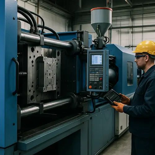
Injection molding is a core manufacturing process used for mass production of complex plastic products, referred to as (production process), with a high degree of repeatability and molding efficiency. The process is capable of molding complex features such as mounting tabs, snap structures, and thin-walled curved surfaces in a single cycle, and has become an indispensable technology in the fields of aerospace, electronics, automotive, industrial equipment, and medical devices.
History of injection molding
Milestone event:1868: John Wesley Hyatt invented “celluloid” (Celluloid), which is the first thermoplastic in history. Made from cellulose nitrate and camphor, it was easy to soften and shape.
1872: Hayat and his brother Isaiah invent the first plunger-type injection molding machine. The machine was extremely rudimentary: heated celluloid was injected into the mold by means of a manual lever. It was primitive, but it laid the groundwork for the three core elements of the injection molding process: heating to soften, pressurized injection, and cooling to set the mold.
Early use of simple manual equipment to process nitrocellulose and other materials. the mid-20th century, with the introduction of screw-type injection molding machine and ABS, nylon, polycarbonate and other engineering plastics to promote the application of injection molding from the production of daily-use products and gradually expanding to the manufacture of industrial functional parts.

Modern mold manufacturing technology continues to evolve:
-
CNC machining to achieve precision mold manufacturing
-
CAE simulation technology accurately predict the filling process
-
Hot runner system effectively reduces material waste
-
Automated control to ensure production stability
Today, the process has been able to ensure that millions of production cycles in the part size and performance of a high degree of consistency.
Several workflows in injection molding
1. Clamping
The mold closes under a calculated clamping force to resist the injection pressure.
2. Injection Molding
Plastic pellets are melted and injected into the cavity at a controlled rate and pressure.
3. Packing and fixing
The material is compressed to counteract shrinkage and at the same time prevent backflow.
4. Cooling
The part solidifies in the mold; cooling time affects dimensional stability and production.
5. Ejector
The ejector pin pushes the solidified part out without causing surface damage.
Of course, the typical cycle time of 8-40 seconds, depending on material properties, part structure and cooling efficiency.
A few common types of injection molding
| Process type | Technical characteristics | Typical application scenarios |
|---|---|---|
| Standard injection molding | Single material, high efficiency | Shell parts, structural components |
| Insert molding | Integrated metal/electronic components | Threaded inserts, sensor bases |
| Dual-material injection molding | Combination of soft and hard materials | Grip, protective trim |
| Gas-assisted molding | Hollow structure, high rigidity-to-weight ratio | Automotive interior parts |
| Liquid silicone molding | Flexible and biocompatible | Medical appliances, sealing products |
The choice of process needs to be a combination of Process selection should take into account the structural requirements, cost budget and assembly program. This is mentioned in the injection molding service, click the link to go.
Mold structure and critical systems
The mold determines the accuracy and productivity of the product.

Typical components include:
-
Geometrically shaped cores and cavities
-
Runners and gates for melt distribution
-
Cooling channels to control shrinkage and reduce cycle times
-
Ejector systems for safe part release
Mold steel grade, number of cavities, surface texture and tolerance levels determine the cost and life of the mold. Cooling efficiency can determine more than half of the total cycle time.
Injection Molding Machine Basics
An injection molding machine contains:
-
An injection unit to melt and meter the material
-
Clamping unit for mold force and alignment
Selection of the press size based on the projected area of the part and the required cavity pressure to avoid flying edges or mold damage.
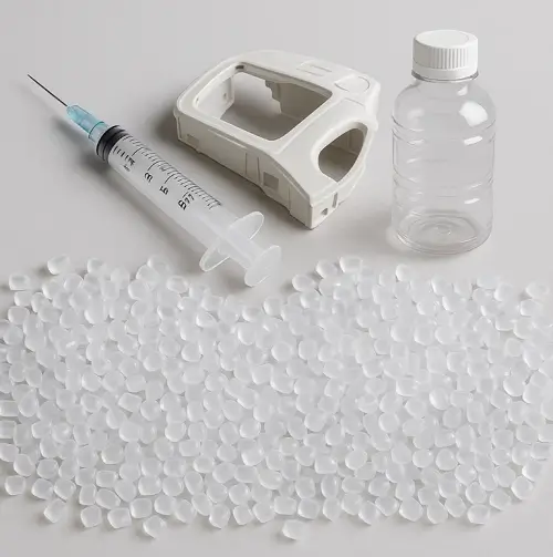
Materials used in injection molding
Examples of commonly used injection molding materials and applications (engineering perspective)
| Material | Engineering properties (brief description) | Application industry | Typical part examples |
|---|---|---|---|
| ABS | Molding stability, impact resistance, moderate heat resistance | Consumer electronics / industrial equipment | Housings, interior panels, mounting brackets |
| PC | High toughness, optically clear optional | Automotive / Lighting / safety parts | Lamp shades, transparent shields, airline seat fasteners |
| PC+ABS | Balance of toughness + processability | Medical / Electronics | Medical housings, laptop housings, in-vehicle control panels |
| PA6 / PA66 | High strength, abrasion and heat resistance | Automotive powertrain | Motor covers, catches, gears, oil connections |
| PA66-GF (glass fiber) | High rigidity, dimensional stability | Automotive structural components / industrial transmissions | Engine compartment function brackets, structural connectors |
| POM | Extremely low friction, fatigue resistant | Precision machinery / automotive | Gears, sliders, bushings, locking mechanisms |
| PP | Lightweight, chemical resistant | Packaging / Home Appliances | Container caps, fittings, water filtration components |
| HDPE/LDPE | High toughness, crack resistance | Packaging / Medical | Medical consumables, squeeze bottles, food containers |
| PS/HIPS | Good surface rigidity | Home Appliances / Consumer Products | Display frames, toys, adapters |
| TPE/TPU | Highly elastic, encapsulated adhesion | Medical / Consumer Electronics | Handle wraps, seals, cable jacketing |
| PMMA | Highly transparent, good weatherability | Optics / household | Transparent panels, lenses for lamps |
| Plasmonic bundles | Strong electrical insulation | Automotive electronic controls / connectors | Plug housings, sensor housings |
| PPS/PEEK | Extreme thermal and chemical stability | Aerospace / medical implants / high temperature environments | Valves, aerospace fixtures, orthopaedic positioning components |
| PVC | Flame-retardant, excellent electrical properties | Electrical protection | Cable ducting, sheathing, low-voltage electrical |
Shrinkage, moisture absorption, UV exposure and flame retardant requirements should be considered during design.
Design Guidelines for Injection Molded Products
The manufacturability of injection molded parts determines the subsequent yield and cost. First of all, control wall thickness uniformity, try to maintain a single thickness under the premise of meeting the strength, the transition with large rounded corners to ease the material flow and stress concentration;
local thickening will cause cooling difference and shrinkage marks, rather than enhance the rigidity of the rib position, the common ratio of 0.5-0.7 × the main wall thickness, and with the parent body to leave a 0.25-0.5mm unloading slot to avoid wrapping rib. to avoid wrapping tendons.
The release slope is ≥0.5° for the outer surface and ≥1° for the inner cavity, and the appearance surface with etching needs additional slope to ensure the appearance. Structures involving inverted buckling are preferred to be avoided by design optimization, followed by the consideration of slider, slanting top, line position and other mechanisms for release, to avoid increasing the complexity and maintenance cost of the mold.
The gate location should be far away from the critical appearance and weak areas, taking into account the mold filling balance and the fusion line hiding; the parts with inserts pay attention to the thickness and symmetry of the package to avoid eccentric shrinkage and cracking. All the rules should be solidified into marking and process constraints at the DFM stage to reduce mold rework.
Dimensional Tolerance & Accuracy
Dimensional stability is determined by material shrinkage, mold temperature and cooling equilibrium, and mold accuracy. 0.4-0.7% shrinkage is common for ABS, 1.0-2.5% for PP, and PA66-GF is more significantly affected by fiber orientation (0.2-0.5% and high anisotropy).
When designing, it is necessary to give the direction of orientation and benchmark positioning. Production through the mold temperature control in ± 1-2 ℃, heat balance verification and cooling circuit isometric arrangement to reduce the batch to batch drift; the key dimensions of the steel compensation and cavity pre-shrinkage design, the assembly surface and the positioning of the reference tolerance should be given to the assembly matching verification program.
Incoming materials should be dried according to specifications, back pressure and screw speed setting in metering section to keep the melt stable; measuring and checking tools and CMM should be reviewed at constant temperature, CPK≥1.33 capacity requirement should be implemented for important features, and the trend chart should be periodically reviewed during mass production period to identify the drift in advance.
Surface Finishing
Appearance quality is set from the mold design. Mirror optics corresponds to SPI A1/A2 polishing level, parting line position should avoid visible area and set up slight inversion to ensure fit; etching/sandblasting can hide slight fusion marks and shrinkage marks, and at the same time enhance the grip friction feeling, but it will magnify the need for mold release tilt.
Parts requiring spraying, pad printing, silk screen printing should reserve process windows on material and surface energy to avoid insufficient paint adhesion; laser engraving is commonly used for glow-in-the-dark buttons and long-term wear-resistant markings, which need to be matched on substrate color and coating system; electroplating/chromium plating has high requirements on material and pre-treatment, and the sprue/parting line must be concealable. All surface solutions should form the “Appearance Quality Standard” (Defect Sample Book + Acceptable Range), to ensure that the trial mold audit signature has a basis to rely on.
Common Defects & Troubleshooting
Short shot/lack of glue is mostly caused by high flow resistance or poor exhaust, which can be improved by increasing the material temperature, injection pressure and injection speed, enlarging the gate cross-section or increasing the exhaust groove;
Silver wire/gas streak is usually caused by hygroscopic materials or volatiles not exhausting, strict drying curve, increase back pressure and prolong holding pressure exchange can reduce gas entrapment;
Scorch is usually caused by high speed shear and poor exhaust, need to optimize the mold filling speed curve, make up the exhaust at the end and reduce the melt residence time;
Shrink marks are caused by thickness difference and insufficient holding pressure. Priority should be given to structural lightening, replacement of thicker tendons, prolonging holding pressure and lowering mold temperature for balanced cooling;
Warpage is related to uneven orientation and shrinkage, which can be solved by symmetrical gating, balanced cooling, fiberglass orientation guidance, and post-drying and humidity adjustment.
The key is to establish a “process window” (upper and lower limits of temperature, pressure, and time) at the T0/T1 stage to stabilize the yield in the middle of the window.
Cost Factors and Optimization
Injection molding costs are comprised of mold inputs, material and wear and tear, cycle time, labor/automation, and throughput/number of cavities. Cooling time is usually the largest part of the cycle time, so optimizing water lines, improving mold temperature stability and hot runner design can significantly reduce the cost per part.
Fast prototyping and mold changeover efficiency should be prioritized in the small batch stage to avoid over-investment, and multi-cavity molds and automated pick-and-place/insert loading should be evaluated after the batch is confirmed. Material side through the lightweight, common grade, reduce color powder switching to reduce losses; tooling fixtures and error-proofing fixtures reduce rework and labor dependency. The overall strategy is to exchange front-end DFM and standardization for back-end capacity and stability.
Quality & Standards
Quality control covers incoming materials, process and shipment. Incoming materials are subject to sampling inspection for moisture content, melting index and color difference; in the process, first piece + inspection + final inspection are carried out to close the loop for key dimensions; before shipment, the reference dimensions are reviewed by CMM/projector/profiler and complete batch traceability is kept.
Depending on the industry, we implement appropriate systems for export business: ISO 9001 for general manufacturing, ISO 13485 for medical related and keep traceable records; material and surface treatment compliance needs to meet RoHS/REACH and other environmental regulations. Establish PPAP/FAI first article approval process and sample retention system for important customers to ensure consistency in mass production.
Sustainability
The core of sustainability strategy is to reduce material and energy consumption per unit of product. Priority is given to the use of PCR recycled materials and bio-based materials in feasible formulations, and hot runners to reduce the number of cold material spouts; lightweighting and modularization are promoted in the structure to reduce non-functional volume; the production line introduces automatic recycling of waste corners and weighing and monitoring, and the ratio of returned materials is controlled by data; the equipment side reduces energy consumption per cycle by insulating, more energy-efficient servo systems linked to the mold thermostat. For external markets, we provide material compliance reports and carbon footprint data, which helps us enter the European and American supply chains.
Examples of Industry Applications
Automotive emphasizes dimensional consistency and weatherability, such as instrument panels, lighting components, and functional brackets, often with thermal cycling and salt spray testing;
The medical field focuses on biocompatibility and cleanliness, with common handheld diagnostic housings and disposable consumables, which need to be sterilized and traceable;
Electrical and electronics focus on flame retardancy, heat resistance and assembly efficiency, such as connectors, buttons, housings, need to take into account the UL rating and appearance quality;
Industrial equipment emphasizes fatigue life and chemical resistance, typically gears, guides, and functional mounts;
Aerospace emphasizes light weight and high temperature resistance, and high performance materials such as PPS/PEEK are used to secure fixtures and heat-resistant structural components.
In every industry, material grades, dimensional tolerances, life and validation methods should be written into technical agreements to reduce the room for ambiguity.
Frequently Asked Questions (FAQs) on Injection Molding Cooperation
Q1: Does it support mold export?
Support. Mold standards are compatible with HASCO / DME, and BOM, assembly drawings, steel and heat treatment reports can be provided to ensure customers’ smooth mass production in overseas factories.
Q2: What is the MOQ?
We support small-lot trial production of 50 pieces or more. After structural validation, it can be expanded to multi-cavity mold and automated mass production according to demand.
Q3: Can I sign a Non-Disclosure Agreement (NDA)?
Yes, we can. A two-way NDA can be signed at the quotation stage to strictly protect customer’s intellectual property rights through hierarchical management of drawings and documents.
Q4: How long is the delivery cycle?
Depending on the complexity of the product, 2-4 weeks for simple molds to complete the trial mold; mass production delivery is usually 1-3 days/batch, supporting parallel material preparation and fast switching scheduling.
Q5:What engineering file formats are supported?
We support mainstream CAD formats such as STEP, IGS, X_T, DWG, etc. We can also provide Coordinate Measuring Machine (CMM) and dimensional report for shipment.
Q6: Can you provide material and quality certificates?
Compliance documents such as ISO 9001 / 13485, RoHS / REACH, etc. can be provided according to export requirements, and full-process quality traceability records can be kept.