
In modern manufacturing, we engineers are more and more frequently faced with a central problem: how to efficiently and reliably combine the properties of different materials into a single component. Plastic alone may not be strong enough, while all-metal components may be too heavy or costly to carry. It is in response to this need that the Insert Molding process has demonstrated its irreplaceable value. Though not a new technology, its excellence in improving product structural integrity, enabling functional integration, and streamlining assembly processes is driving continued growth in high-end manufacturing applications such as automotive, electronics, and medical. Essentially, it responds to the market’s core demands for component lightweighting, functional integration and production automation. Let’s explore the basic explanation and application areas of embedded molding. If you feel that this article is not written thoroughly enough or there are places where mistakes are made, please feel free to contact us for corrections and answers.
What is Insert Molding
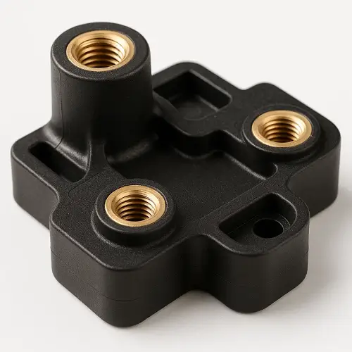
Insert Molding is the process of placing a metal part into a mold (usually a metal part such as a nut, bushing, pin, or finished part) in advance of injection molding, precisely placed in the cavity of the injection mold, and then closing the mold and injecting the molten plastic material into the mold so that it is shaped, cooled, and securely bonded around the insert or to a specific area. Finally, the mold is opened and a complete part is produced that integrates metal and plastic, providing new functionality and structural strength. This is a basic insert molding solution.
Common inserts include our brass nuts, steel bushings, shaft parts, electrode terminals, stampings, and more. They have a voice in automotive connectors, sensor housings, electronic structural components, medical grips, industrial equipment mounts, and more.
Flow of Insert Molding
Insert Preparation and Positioning
First, we carry out the necessary cleaning and pre-treatment of metal inserts to ensure that their surfaces are free of oil, dirt and oxidized layer, which can make the bonding strength between plastic and metal increase. Subsequently, the inserts are accurately placed into the pre-set positioning mechanisms (e.g. pins, slots) within the mold by means of automated manipulators or precision fixtures. The accuracy of this step directly determines the fit tolerance and functional reliability of the final product. It is also the step in the first part of the process that requires the most precision.
Mold Closure
When our insert is placed in position, the injection molding machine drives the moving mold to close with the fixed mold to form a closed cavity. The mold design must ensure that the insert is held securely in its intended position without shifting or loosening under high pressure melt impact. The mold closing force must also be set to take into account the change in cavity pressure brought about by the insert.
Injection and Filling
The uniformly plasticized molten plastic is injected into the mold cavity at high speed and high pressure under the drive of the screw. The melt follows the preset runners and gates and surrounds and fills the voids around the insert. During this process, the melt temperature, injection speed and pressure profile need to be precisely controlled to ensure complete encapsulation of the insert while avoiding impact damage or flow defects on delicate inserts such as threads.
Cooling and Curing
Then after the injection is complete, the mold enters the holding and cooling phase. The plastic cures and shrinks in the presence of circulating cooling water, and the holding pressure continues to replenish the material, preventing shrink marks and ensuring a tight fit between the plastic and the surface of the insert. The setting of the cooling time is critical to ensure that the plastic is sufficiently rigid before the mold is opened.
De-molding and post-processing
When cooling is complete, the mold opens and the ejector system ejects the molded part. The removed part usually does not require secondary assembly, but may require simple post-processing such as gate trimming, cosmetic inspection, or functional testing before it can be delivered as a finished product.
Common Insert Types
Brass Threaded Inserts
The most commonly used type, providing a strong, wear-resistant internal thread, widely used for screwed joints in plastic housings.
Steel Parts, Bushings, Contacts
Used for local structural strength, bearing function or electrical connections.
PCB/Electrodes
The entire circuit board or metal pins are used as inserts to encapsulate a waterproof, vibration-resistant electronic module in a single package.
Metal Inserts
such as metal skeleton, reinforcement, used to carry the main load, plastic is used as a cover or connection form.
High-temperature and corrosion-resistant inserts (medical/aerospace)
Stainless steel, titanium alloys and other specialty metals are used to meet the temperature, corrosion and biocompatibility requirements of extreme environments.
Part V: Material Selection for Insert Molding
| Material | Properties | Applications | Notes |
|---|---|---|---|
| ABS | Easy to mold, good all-around performance | Consumer electronics housings | Most commonly used; good compatibility with threaded inserts |
| PC | High toughness, high clarity | Automotive electronics components | Prone to stress cracking; requires tight process and insert design control |
| PA66 / PA6 | Wear-resistant, self-lubricating | Gearboxes, gears, bearing housings | Often used with brass inserts; high moisture absorption; requires adequate drying |
| PA66-GF30 | High strength, high rigidity | Highly loaded structural parts | Glass-fiber reinforced; higher molding temperatures; increased mold wear |
| TPE / TPR | Soft, high friction, elastomeric | Medical handles, tool grips | Used in overmolded designs; ensure chemical compatibility with PC/ABS substrates |
Insert Molding Design Guidelines
Wall thickness design
The thickness of the plastic overlay must be uniform. Minimum wall thickness should be at least 1/2 the diameter or thickness of the insert and not less than 0.8mm to prevent shrinkage, stress concentrations and underfilling.
Rounded transition
In the insert and the combination of plastic must be used in the rounded transition (R angle), absolutely avoid sharp corners. Rounded corners are effective in dispersing stresses, improving melt flow and preventing cracks.
Direction of flow
The gate should be positioned so that the melt flows parallel to the long axis of the insert, rather than impacting perpendicularly, to minimize the risk of displacement of the insert and to ensure good encapsulation.
Mold Pull-Out Slope
Design the mold pull-out slope (usually 1°-3°) in the plastic part around the insert to ensure smooth mold release and avoid scratching the product.
Reinforcement design
The thickness of the reinforcement near the insert should not exceed 50%-60% of the main wall thickness to prevent visible shrink marks on the backside.
Anti-displacement positioning
Reliable positioning mechanisms must be designed in the mold for the insert, such as locating pins, grooves, magnetic holders or knurled structures, especially when the axis of the insert is in the same direction as the mold opening.
Tolerance chain design
Tolerance chain analysis should be performed to ensure the accuracy of the final assembly dimensions, taking into account insert tolerances, mold tolerances and plastic shrinkage.
Shrink Mark Avoidance
Eliminate localized material buildup and shrink marks caused by inserts by using fan gating in thick wall areas, adjusting holding pressure, or modifying the product structure (e.g., undercutting).
Insert Temperature Control
At high production speeds, inserts can be pre-heated (to reduce internal stresses) or pre-cooled (to protect precision features) to control thermal shock during molding and avoid warpage and thread distortion.
Industry Applications for Insert Molding
Automotive
In the automotive sector, insert molding is mainly used for functional parts with structural strength and environmental resistance, such as sensor housings, ECU connectors, light modules, etc. Metal nuts and steel inserts provide reliable assembly points for plastic parts and prevent loosening after long periods of vibration. For parts around the transmission, insert molding adds metal reinforcement zones to oil- and heat-resistant engineering plastics to keep parts stable in high-temperature and shock environments.
Consumer Electronics
Consumer electronics products have high demands on exterior dimensions, thin-walled structures, and assembly precision, so insert molding is often used to add a nut fixing point in the plastic center frame to improve durability during repeated disassembly. Structures such as screen pivot supports for laptops and wearable device housings also have metal parts embedded in the plastic to increase torsional and tensile resistance. Embedded molding allows products to be lightweight while maintaining sufficient mechanical strength.
Aerospace
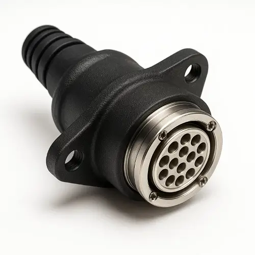
Aerospace components are often lightweight and need to meet stringent temperature, corrosion and fatigue resistance requirements. Insert molding is often used in these applications for cockpit control components, cable connectors, and other structures, where high performance engineering plastics are wrapped around specialty metal inserts to achieve a combination of low weight and high reliability. The process reduces the number of assembly points and improves system safety at the source.
Medical Devices
Insert molding is widely used for medical devices that emphasize stability, chemical resistance, and hand comfort. For example, surgical instrument handles have a metal core embedded in a plastic shell to provide both strength and surface grip. Some disposable endoscopes or insulin pump housings are also insert molded to achieve a hermetically sealed structure that maintains consistent performance over repeated sterilization or long-term use.
Industrial Equipment
Industrial equipment requires greater durability and structural strength, so insert molding is commonly used for locations such as high-strength connectors, motor end caps, and instrumentation mounts. Metal inserts significantly increase the reliability of plastic parts under stress, vibration, and temperature changes. For equipment that requires long term stability, this type of construction reduces the need for maintenance and improves overall system life.
Insert Molding vs Overmolding
| Characteristics | Insert Molding | Overmolding |
|---|---|---|
| Core Concept | Inserting metal or prefabricated rigid parts into plastic during the molding cycle | Molding a second material (usually soft elastomer) over an existing plastic substrate |
| Primary Purpose | Enhance localized strength, functionality, and simplify assembly | Improve feel, aesthetics, sealing, anti-slip, and vibration damping |
| Process | Typically one-step: inserts are placed and molded in a single shot | Two-step: substrate molded first, then overmolded in a second shot |
| Material Combinations | Metal + Plastic, or Rigid Plastic + Plastic | Rigid Plastic (e.g., PC, ABS) + Soft Elastomers (e.g., TPE, TPU, Silicone) |
| Typical Products | Plastic parts with threaded inserts, connectors with pins | Power tool grips, toothbrush handles, consumer electronics cases |
Insert Molding Common Defects & Engineering
Metal Part Offset
Optimize the positioning and fixing of the insert in the mold; adjust the gate position so that the melt flow does not directly impact the insert.
Bubbles/voids
Increase mold venting; optimize injection speed and use segmented injection; preheat the insert to remove water vapor adsorbed on the surface.
Thread deformation due to overheating of the nut: Reduce the melt temperature; use internal cooling needles or pre-cool the insert; shorten the injection and holding time.
Material flow lines
Adjust the location or number of gates; increase the mold and melt temperatures; optimize the injection speed.
Poor adhesion
Ensure cleanliness of inserts; roughen inserts by sandblasting, knurling, etc.; use specialized adhesives if necessary.
Our Insert Molding Capabilities
Based on many years of engineering practice, we have accumulated reliable technical solutions for this process. Our capabilities cover a range of injection molding machines from 80 tons to 1,800 tons, and we are able to respond to the production needs of small precision electronic parts to large industrial structural parts. We are particularly adept at the precise and efficient positioning of inserts through automated robots to ensure production stability and consistency. In terms of dimensional control, we are able to achieve a tolerance of ±0.02-0.05 mm between the insert and the plastic part by virtue of precise mold manufacturing and process control. In pre-production, we routinely use Mold Flow Analysis software to simulate the filling, cooling and shrinking processes of plastics to pre-identify and optimize potential areas of incomplete coverage, air pockets and stress concentrations. Additionally, our flexible production model allows us to meet our customers’ needs for small pilot runs and rapid iterations, as well as large-scale mass production deliveries.
FAQ
What metals can be used for Insert Molding?
Almost any engineering metal can be used, such as brass, steel, stainless steel, and aluminum. The choice depends on a combination of strength, corrosion resistance, electrical conductivity, cost and weight. Brass is most commonly used for its machinability, thermal conductivity and rust resistance.
Will the nut come out of the plastic?
Not if they are properly designed. We ensure this through structural design, such as knurling, grooves, holes, etc. on the inserts, which allow the plastic to flow in and form a mechanical interlock, with much higher resistance to twist-out and pull-out than traditional press-in or ultrasonic implantation methods.
What is the cost difference compared to normal injection molding?
Costs are typically higher, primarily in: the cost of the metal insert itself; increased insert handling and positioning processes (automated equipment investment); more complex mold design; and longer cycle times for single-piece production (time to place the insert). However, the advantage is that it saves the subsequent assembly cost and the cost of screws, glue and other auxiliary materials, and improves the overall quality and reliability of the product, which is often a better choice from a total cost perspective.
Is it possible to do automated loading?
Yes, it is possible. For inserts with regular shape and large batch size (e.g. standard nuts), we prioritize the use of automated loading system, together with visual inspection or mechanical positioning, to achieve fully automated production, which greatly improves the efficiency and reduces human error.
How to avoid cracks due to the big difference in properties between plastic and metal?
The key lies in design control and process optimization: Ensure sufficient plastic cladding thickness; make sufficient rounded transitions at all sharp corners; choose plastics with lower shrinkage and better toughness (e.g., PC instead of brittle PS); preheat the inserts to reduce thermal stresses; and strictly control the cooling rate.
We hope this technical guide will be helpful in your engineering evaluation and decision-making. If you have a project under development or require insert molding support, you are welcome to discuss the technical details with us. For cost estimation or feasibility review, you may also contact us directly to obtain a preliminary quotation.