Draft angle is one of those details that looks small in CAD but shows up fast in the mold shop. A part can still come out of the tool with very little draft, and that is exactly why some teams underestimate it. The real problem is not whether the part ejects once. The real problem is what that low draft costs in production. Higher ejection force, drag marks on cosmetic walls, polished steel that starts to wear, texture that scuffs, and dimensions that move once the tool begins to run harder. Those are the issues that turn a simple design decision into a tooling correction.
In practical injection molding work, draft is not just a textbook rule. Draft is part of release control. A plastic part with proper draft tends to release more cleanly, hold appearance better, and put less stress on both the mold and the part during ejection. A plastic part with marginal draft may still survive trial, but it often becomes less forgiving when volume increases, cosmetic standards tighten, or a textured finish is added later.
For most smooth production parts, 1° per side is a safe starting point. Some walls can run with less, and some features need much more. The right answer depends on surface finish, feature depth, resin shrink, core pull direction, and how the part is expected to release from the steel.
Quick Reference for Injection Molding Draft Angle
| Feature or condition | Practical starting point |
|---|---|
| Smooth external wall | 0.5° to 1° per side |
| General production wall | 1° to 2° per side |
| Internal walls on a core | 1° to 2° per side |
| Ribs | 0.5° to 1° per side |
| Bosses | 0.5° to 1.5° per side |
| Light texture | around 2° per side |
| Heavy texture | 3° to 5° or more per side |
| Deep shut-off or long sealing surface | case by case, often more than a standard wall |
| Clear cosmetic parts | usually benefit from more generous draft |
These are starting values, not fixed rules. The final draft angle for injection molding should always be reviewed with part depth, material, texture, polish, and ejection method in mind.
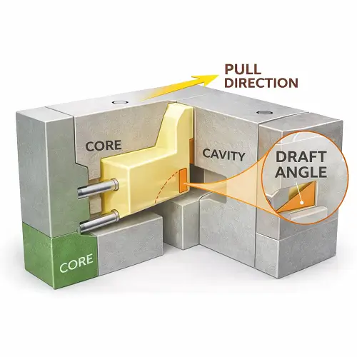
What Is Draft Angle in Injection Molding?
What is a draft angle? In injection molding, draft angle is the slight taper added to a wall or feature in the direction of mold opening so the part can release from the cavity or core more easily. Instead of a perfectly straight wall, the geometry leans slightly. That small change reduces the contact and friction between plastic and steel during ejection.
Some designers search this as injection molding draft angle. Others search draft angle in injection molding, injection mold draft angle, or injection moulding draft angle. The wording changes, but the design function stays the same. Draft helps the part separate from the mold with less force and less surface damage.
A zero-draft wall can look clean in the model, especially if the part is simple. In the actual molding process, the plastic cools, shrinks, and grips the steel. Internal walls shrink around the core. Textured surfaces create more drag. Deep features increase contact length. What looks acceptable on screen may become difficult in production.
Why Draft Angle Matters in Real Production
Designers often treat draft as a release aid only, but its effect is wider than that. Draft influences ejection force, cosmetic quality, steel wear, process consistency, and tool maintenance.
When draft is too small, the press can still eject the part, but the release becomes less controlled. Ejector pins push harder. Thin walls may flex. On some materials, you start seeing white stress marks around pin locations. Cosmetic walls show drag or gloss change. Textured surfaces come out looking rubbed or scarred. In deeper geometry, the part may hesitate on the core and then jump free. That sudden release is usually not a sign of good design.
This is one reason good plastic molding design is not only about filling the part. It is also about getting the part out of the mold repeatedly without damaging the part or beating up the tool.
In automotive plastic injection mold programs, this matters even more. A part may include deep ribs, retention clips, shut-offs, grained appearance surfaces, and tight packaging limits all in one design. If the draft strategy is weak, the mold may still run, but it becomes harder to keep appearance and consistency under control as the tool goes from trial into real production.
How Much Draft Angle Is Needed in Injection Molding?
This is the question that matters most in design review. How much draft angle is actually needed?
For a smooth general-purpose production wall, 1° per side is usually a reliable starting point. If the wall is short, open, polished, and not highly cosmetic, 0.5° per side may still work. Once the wall gets deeper, more cosmetic, or more difficult to eject, 1° starts to look much safer.
Internal walls usually deserve more caution than external walls because the plastic shrinks onto the core. That is where many parts get into trouble. A designer may give the inside and outside the same nominal draft, but the inside feature often needs more help releasing.
For textured surfaces, the answer shifts quickly. A wall that releases well at 1° in a polished tool may need 2° or more after texture is applied. Heavier texture can push the required angle even further. That is why texture and draft should never be finalized separately in plastic part design. A surface finish decision often changes the release requirement.
Feature depth matters too. A shallow wall and a deep sleeve are not the same problem. The longer the molded surface stays in contact with the steel during ejection, the more opportunity there is for drag. Deep features, narrow cores, and enclosed geometry usually need a more generous draft strategy than open part geometry.
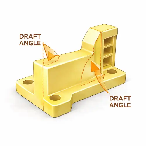
External Walls, Internal Walls, Ribs, and Bosses Need Different Thinking
One of the most common mistakes in injection molding part design is applying one draft number across the entire model and assuming every feature behaves the same way. Real parts do not work that way.
External walls are usually the simplest place to start. If the surface is visible and the finish matters, draft helps protect appearance. A straight wall with low draft may still eject, but that does not mean it will look clean after repeated runs. If the surface will be textured, draft should increase early rather than waiting until T1 to see scuffing.
Internal walls are more demanding because the plastic shrinks onto the core. Cups, sleeves, connector features, and enclosed pockets often need a stronger draft strategy than the outside of the part. This is where release problems hide. At trial, the part may come off, but the ejector load is often higher than expected, and the inside wall may already be telling you the design is marginal.
Ribs also need draft, even though they are thin. A rib with no draft is harder to machine well, harder to vent properly, and harder to eject cleanly. A typical starting point is 0.5° to 1° per side, then adjusted based on rib height and material behavior. Bosses usually fall in a similar range, but tall bosses, deep cores, or shrink-prone materials can justify more.
In real mold reviews, these features are not judged by angle alone. They are judged by height, depth, wall relationship, resin behavior, and how the part is expected to leave the steel.
What Happens When Draft Is Too Small but the Mold Still Runs
This is where many design teams get fooled. A mold with low draft can still run. The first samples may even look acceptable. That does not mean the geometry is healthy for production.
A common shop-floor scenario is this: T1 parts eject, but the ejection force feels heavy. The toolmaker sees polish rub on one side wall. The cosmetic surface looks acceptable in a few early samples, so the part is approved for the next step. Later, once the mold runs longer and the process window tightens, the wall starts showing drag marks or gloss variation. Nothing “failed” in one dramatic way. The design just had too little release margin.
Another common case is an internal feature that looks fine in CAD and even passes dimensional inspection. During actual molding, the part shrinks onto the core harder than expected. Ejector force rises, the part hesitates, and slight deformation starts appearing around a nearby thin wall or pin location. The design technically works, but it is not robust.
That difference matters. Good injection molding design guidelines are not only about whether a part can be molded. They are about whether the part can be molded cleanly, repeatedly, and without hidden process stress.
Draft Angle and Injection Molding Wall Thickness
Draft and injection molding wall thickness should be reviewed together, but they solve different problems.
Wall thickness affects filling, cooling, shrink behavior, and structural feel. Draft affects release. A thick wall does not eliminate the need for draft. In some cases, thicker walls make overall molding behavior worse by increasing sink or uneven cooling, while still dragging on the steel if the taper is missing.
A thin wall does not eliminate the need either. Thin sections can still stick, and when they do, they are often more likely to distort during ejection because they do not resist the force as well. That is why injection molding wall thickness and draft angle should never be optimized separately.
The same logic applies to injection molding minimum wall thickness. Minimum wall thickness guidelines help determine whether the resin can fill and pack the feature effectively. They do not tell you whether the feature will release well. A wall can be within thickness guidelines and still be a poor molding candidate if the part has little draft, deep geometry, or a difficult pull direction.
The trade-off becomes more obvious on locating surfaces, assembly walls, and functional internal diameters. In those areas, adding more draft may improve release but also change how the part fits, seals, or aligns with another component. That is why draft should be reviewed together with dimensional strategy, not after it. On tight assembly features, the best solution is often a balance between molding release, tolerance control, and the function of the finished part.
Clear Plastic Molding Needs Better Release Control
Clear plastic molding usually exposes draft problems faster than opaque parts. A part that seems acceptable in black or gray resin may show scratches, drag lines, or gloss inconsistency immediately when molded in transparent material.
That is why clear parts often benefit from more generous draft, better polish, and more conservative release design. A polished cavity alone is not enough if the geometry still drags hard during ejection. On clear parts, the mold may technically release the part, but even light surface scuffing can be visible to the customer.
When a part has optical surfaces, transparent walls, or appearance-critical clear features, draft angle should be reviewed as part of appearance protection, not only as a molding convenience.
Shut-Off Areas Need More Than Standard Wall Draft Rules
Draft becomes more sensitive around injection molding shut off features. Shut-offs are steel-to-steel sealing areas used to block plastic flow or form windows, clips, side openings, and detailed geometry. They are not ordinary walls.
A long shut-off with weak angle strategy can wear faster, flash sooner, and create fitting problems in the tool. Sharp shut-offs may be fragile. Deep shut-offs can become difficult to machine and maintain. This is one area where generic online numbers stop being useful very quickly.
For shut-off design, the mold builder is not only thinking about release. The mold builder is thinking about sealing, steel strength, wear resistance, alignment, and service life. That is why injection mold tooling standards and mold construction experience matter so much here. A shut-off cannot be designed as if it were just another cosmetic wall with a simple taper added later.
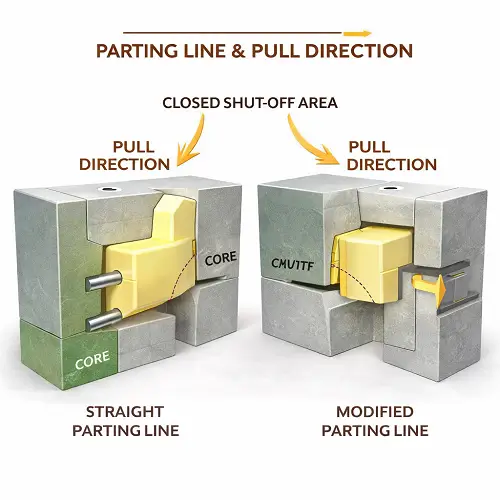
When a part includes side openings, clip windows, hidden snap details, or complex parting geometry, the draft review should happen together with shut-off review and parting-line strategy.
Sometimes the real issue is not the draft number itself, but the pull direction chosen at the beginning of the mold layout. A wall may appear to have enough taper in CAD, yet still become difficult to mold if the parting strategy forces the feature into the wrong opening direction. In those cases, adding more draft is not always the best fix. The better solution may be to change the parting line, use a slider or lifter, or modify the geometry so the feature works with the mold instead of against it.
Draft Angle Should Be Clear in Mold Drawings and DFM Review
A lot of molding problems start because draft was assumed instead of defined. In a good DFM review, the team should know the pull direction, know which faces are cosmetic, know which features shrink onto the core, and know where release margin is tight.
Mold drawings and part files should make those decisions clear. If the CAD model leaves too much to interpretation, the industrial designer, product engineer, and toolmaker may each picture a different release condition. That is where expensive misunderstandings begin.
A practical review usually asks straightforward questions. Which surfaces are carrying texture? Which internal features are deep enough to hold the core tightly? Are there tall ribs or bosses with marginal draft? Is the current geometry relying on polish to solve a release problem? Are there shut-offs that need steel safety more than nominal appearance?
That kind of review is far more valuable than copying a generic ejection angle chart into the project folder and assuming the issue is covered.
Prototype Tools and Production Tools Do Not Judge Draft the Same Way
A prototype mold can sometimes tolerate draft that would not be considered healthy in production. The shot count is lower, the team watches the tool more closely, and some manual intervention may be acceptable. That often gives the false impression that the design is ready.
Once the same part moves toward higher volume, the standards change. The mold must cycle more consistently. Appearance matters more. Steel wear matters more. Tool maintenance becomes part of the cost picture. A design that survived a prototype tool may become a problem once it is asked to behave like a production part.
That is why designing for injection molding should not stop at “the part came out.” The better question is whether the part can keep coming out cleanly at the volume and appearance level the project really needs.
A Practical Way to Choose Draft Angle Early
A useful rule in early plastic part design is to judge draft by function, not by habit.
If the wall is cosmetic, protect appearance first.
If the wall is internal, expect more grip on the core.
If the feature is deep, add margin.
If the surface is textured, increase draft early.
If the feature is a shut-off, review the steel condition before freezing the geometry.
If the part is clear, assume surface damage will show sooner.
That approach usually gives better results than trying to force one number across the whole model. Draft angles for injection molding are not decided by a single chart. They are decided by surface condition, release direction, depth, resin behavior, and tool construction.
Conclusion
Injection molding draft angle is one of the clearest examples of a small CAD decision creating a large manufacturing effect. When draft is handled well, the part releases more cleanly, cosmetic quality is easier to hold, ejection loads stay lower, and the tool has a better chance of running consistently. When draft is handled poorly, the mold may still run, but it usually runs with less margin and more hidden stress.
That is why draft should be reviewed together with wall thickness, ribs, bosses, texture, clear surfaces, pull direction, and shut-off geometry before steel is cut. Fixing draft on screen is easy. Fixing it in hardened tooling is not.
JeekMould supports plastic molding design, DFM review, mold building, and production for custom plastic parts. If a project includes deep walls, cosmetic surfaces, internal cores, or difficult shut-off features, send the CAD files to JeekMould before the mold design is released. A draft review at that stage usually saves far more time than trying to solve release problems after trial.
FAQs
What is a good draft angle for injection molding?
For many smooth production walls, 1° per side is a practical starting point. Some short polished walls can work at 0.5°, while textured or deeper features often need 2° or more.
Why do internal features usually need more draft?
Internal features shrink onto the core, so they tend to grip the steel more strongly during ejection. That is why sleeves, pockets, and enclosed geometry often need more release margin.
Do ribs and bosses need draft angle?
Yes. Ribs and bosses should not be designed straight. Even small features benefit from taper because they still contact the steel and still need to release cleanly.
How does texture affect draft angle?
Texture increases friction between the molded part and the mold surface. A wall that works in a polished mold may need significantly more draft once texture is added.
Can a part run with very little draft?
Sometimes it can, especially in trial or low-volume tooling, but that does not always mean the design is robust. Low draft often shows up later as drag marks, heavy ejection, cosmetic variation, or tool wear.