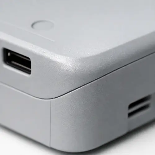
A molded plastic part can look perfectly clean in CAD and still show a visible seam once it comes out of the tool. Sometimes that seam is light enough to disappear into an edge or corner. Sometimes it runs across a glossy surface and becomes one of the first details people notice. Once that happens, the questions are usually the same. Is this normal? Can it be removed? Why does one part look clean while another shows a visible line, slight mismatch, or even flash along the seam? And why does such a small detail on the plastic part seem to affect the mold so much?
That visible seam is usually the parting line. In injection molding, the parting line is not just a line left on the surface after molding. It is tied to how the mold opens, how the steel shuts off, how the part is released, and how easy it is to keep appearance under control in production. A small change in parting line location can improve the look of a housing, or it can push the tool into a more difficult and more expensive direction.
This is why parting line decisions should never be left until the end of part design. On some parts, the line can be hidden on an edge, folded into a contour, or placed where it does not interrupt the main visible face. On others, trying too hard to hide it creates a harder mold, a weaker shut-off area, or more flash risk than expected. The line itself is simple. The decision behind it usually is not.
What Is a Parting Line in Injection Molding?
A parting line is the seam created where the two halves of an injection mold meet and separate. Every molded part needs some way to come out of the tool after the plastic fills and cools, so a meeting boundary has to exist somewhere on the part. That boundary becomes the parting line.
On a small internal bracket, the line may barely matter. On an exterior housing, a control panel, or a cosmetic cover, it matters a lot more because it becomes part of what the finished product looks like. That is why the same line can be treated as routine on one part and unacceptable on another. The line itself is normal. What changes is where it lands and how visible it becomes.
It also helps to separate a normal parting line from a quality problem around the parting line. The seam is expected. Flash, sharp burrs, mismatch, or an obvious raised edge are not. In other words, the existence of a parting line does not mean the molding is poor. The real question is whether the line was placed well and whether the tool is holding it cleanly.
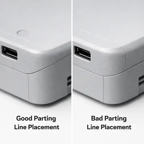
A good parting line usually follows the shape of the product and stays out of the areas where appearance matters most. A poor one cuts across the wrong face, interrupts reflections, or ends up in a location that makes the part look rougher than it really is.
Why Do Injection Molded Parts Always Have a Parting Line?
The mold has to open. That is the basic reason parting lines exist.
As long as a plastic part is being formed between mold halves, those halves need a place to meet while the cavity is closed and a direction to separate when the cycle is finished. That is why a seam is normally unavoidable in injection molding. The more practical goal is not to eliminate the parting line completely, but to control where it appears and how noticeable it becomes on the finished part.
That difference matters. A line placed on a sharp corner or natural break often fades into the shape of the part and causes little concern. The same line across a polished front face can immediately draw attention and make the surface look interrupted. On parts with tighter appearance expectations, the seam is judged less by its size than by how it interacts with the visible geometry around it.
This is also why some molded parts seem to have almost no visible seam while others show one clearly. The line may be similar in both cases. What changes is the surface, the lighting, the texture, and the way the parting line was positioned during mold design.
Why Parting Line Placement Matters More Than It Seems
A parting line can look like a small detail in the model and still influence much more than expected once the mold is being designed. Where that line sits affects the opening direction, the shut-off condition, the ease of flash control, and the amount of freedom available in the rest of the tool layout.
That is where appearance and mold design start pulling against each other. A location that looks cleaner on the product may create a more complicated shut-off or a less stable mold condition. A location that makes the tool easier to build may put the seam exactly where it is easiest to see. The best result usually comes from balancing those two sides early instead of chasing one and paying for it later.
This becomes more obvious on housings, covers, and visible shells. A seam tucked into an edge, texture break, or shadow line is usually far easier to live with than one that runs through a broad flat face. At the same time, moving the line away from the most natural split can change how the mold opens and how robust the steel condition will be in production. What looks like a small layout decision on screen can turn into a tooling decision with real cost and quality consequences.
How Parting Line Affects Product Appearance
Appearance is where the parting line gets judged most harshly. On hidden structural parts, the seam is often just another molding detail. On outer shells, visible panels, glossy covers, and cosmetic housings, it becomes part of the product’s visual quality whether anyone planned for it or not.
The difference is usually not whether the line exists. It is where it runs and how the surrounding surface reacts to it. A seam on a corner often disappears into the geometry. A seam across a flat polished face can interrupt reflections, create a shadow line, or make the two sides of the surface feel visually broken even when the dimensions are technically acceptable.
That sensitivity becomes even stronger on high-gloss plastics, transparent parts, and smooth consumer electronics housings. A small mismatch or faint seam that might be tolerated on a textured industrial cover can stand out immediately on a polished visible shell. Once that happens, the seam stops reading as a normal molding mark and starts reading as a defect, even if the process itself is otherwise under control.
This is why parting line placement should be discussed while the product form is still flexible. Once the exterior shape is finalized and the mold direction is already constrained, the options become narrower. By then, the seam can usually still be moved, but not always to a location that is good for both appearance and tooling.
Parting Line, Flash, and Mismatch: What Usually Goes Wrong
A visible seam is one thing. A seam with flash or mismatch is another.
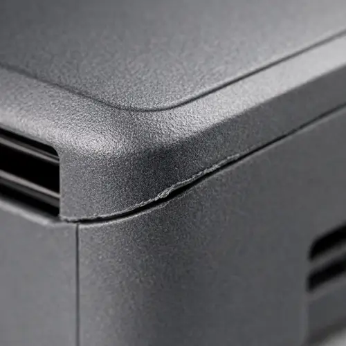
Flash is one of the most common reasons a parting line becomes a quality complaint instead of a normal molding feature. When the shut-off condition is weak, when the mold halves are not sealing as cleanly as they should, or when wear starts to build up in the steel, molten plastic can creep into the split and leave a thin raised edge. On some parts, that edge is only slightly visible. On others, it feels sharp enough to catch a fingernail and immediately makes the part look poor.
Mismatch creates a different kind of problem. Instead of a thin burr, one side of the seam may sit slightly higher than the other. The step may be small, but on a visible housing it often shows up more clearly than expected. A polished surface makes that even worse because light catches the transition and turns a minor offset into a noticeable visual defect.
What makes these problems frustrating is that the seam itself often gets blamed first, when the real issue is usually steel condition, shut-off length, mold wear, clamping consistency, or a parting line that was placed in a difficult area to begin with. A seam crossing a broad cosmetic face or a long sensitive shut-off is always going to be harder to control than one tucked onto a safer edge.
In practical terms, flash and mismatch are what turn a normal parting line into a visible quality problem. That is why the seam location should never be judged only by how it looks in CAD. It also has to be judged by how stable that region will be once the tool is running.
How Parting Line Placement Affects Mold Design and Tool Cost
The parting line may look small on the plastic part, but in the mold it can influence almost everything. It affects how the mold opens, how inserts are arranged, where shut-offs occur, how flash is controlled, and whether the tool remains simple or starts requiring more complicated geometry.
A common situation is trying to hide the seam from the most visible face of the part. On the surface, that sounds like the right choice. In some cases it is. In others, moving the line away from the natural mold split creates a more difficult shut-off, adds sensitivity to steel alignment, or forces the mold into a less stable opening strategy. The part may look cleaner in one viewing angle, but the tool becomes more demanding to build and maintain.
That tradeoff matters because the mold is not only being judged on whether it can make the part once. It has to make the part consistently. A parting line location that looks better in the CAD model may lead to more polishing, tighter fitting, more maintenance, or more flash risk over time. A line placed in a more practical location may be easier to control, cheaper to tool, and more stable in volume production.
This is one of the reasons parting line review belongs in DFM, not as a final cosmetic adjustment after the rest of the part is already fixed.
What Designers Should Consider Before Locking the Parting Line
The first question should be simple: where will the seam be most visible? If the line crosses the main front face, a large polished panel, or an area that catches light directly, appearance issues are much more likely. On the other hand, if the line can follow an edge, transition, shadow line, or texture break, it often becomes far easier to manage visually.
The second question is whether the line crosses any functional surface. A seam through a sealing area, a fit-critical region, or a controlled assembly interface can create more than a cosmetic issue. Even a small amount of mismatch or flash can begin to affect how the part fits, seals, or feels in use.
The third question is whether the chosen location works with the mold opening direction. If the seam is placed where the part naturally wants to split, the mold usually stays simpler and more stable. If the line is forced into a less natural path only for appearance reasons, the mold may need more careful shut-off control, more inserts, or a more delicate steel condition than the project really wants.
Good parting line decisions usually come from looking at all three of these issues together. Appearance matters. Function matters. Moldability matters. The seam location has to live with all of them at the same time.
A Realistic DFM Example: One Housing, Two Very Different Outcomes
A rectangular consumer housing is a good example because it looks simple until the seam location is actually reviewed. The most natural parting line may run around the side wall and break at the outer edge. That is usually good for mold opening, steel shut-off, and long-term stability. The mold stays cleaner, the seam can be controlled more easily, and flash risk is lower.
Then the appearance requirement changes. The visible side wall is no longer acceptable as a seam location, so the line is pushed farther back or redirected to protect the main viewing surface. On the CAD model, that often looks like an obvious improvement. The front-facing shell looks cleaner. The seam is less visible from the outside.
The problem is that the mold may now need a longer or weaker shut-off, tighter steel fitting, or a more sensitive split around ribs, clips, or side geometry. What looked like a simple visual improvement becomes a tooling tradeoff. Flash control gets harder. Polishing time goes up. Maintenance becomes more important. In some cases, the seam that was hidden from one angle creates a worse production condition overall.
This is the kind of decision that separates an acceptable mold from a stable mold. A slightly more visible seam in a safer location often produces a better real-world result than a perfectly hidden seam that pushes too much risk into the tool.
How to Make a Parting Line Less Visible on Plastic Parts
In most projects, the goal is not to erase the seam completely. The goal is to make it less noticeable.
One of the most effective methods is to place the line on a corner, break line, edge, or contour that already exists in the design. A seam hidden inside a natural transition almost always performs better visually than one stretched across an open cosmetic face. On textured parts, the seam can also blend more easily than it would on a glossy polished surface.
Surface finish makes a big difference here. High-gloss plastics tend to show parting lines more clearly because reflections are more easily interrupted. Textured surfaces can hide minor line visibility better, although that does not excuse a badly placed seam. Transparent parts are even less forgiving. In those cases, the line needs to be planned very carefully because even a small seam can remain obvious.
A practical design habit is to stop thinking of the seam as something to remove later. It is much easier to design around it from the start. Once the tool direction, shut-off strategy, and part geometry are already fixed, improving visibility becomes much harder.
Parting Line Design Review Checklist
Before locking the mold strategy, it helps to review the seam as both a product feature and a tooling feature.
| Review Item | What to Check | Common Risk |
|---|---|---|
| Parting line location | Does the seam cross a cosmetic face? | Visible line, poor appearance |
| Mold opening direction | Does the part split naturally? | More difficult tooling, unstable shut-off |
| Functional surfaces | Does the line cross a sealing or fit area? | Leakage, mismatch, assembly issues |
| Shut-off condition | Is the steel contact long or sensitive? | Flash, wear, maintenance |
| Surface finish | Is the seam on a glossy or transparent area? | Higher visual sensitivity |
| Geometry transitions | Can the line follow an edge or break line? | Better seam control and appearance |
A short review like this often reveals the real problem early. In many cases, the issue is not that a parting line exists, but that it ended up in the wrong place for the part’s visual or functional priorities.
What Matters Most Before Releasing the Design
A parting line should not be judged only by whether it is technically possible. It should be judged by whether it still makes sense after appearance, function, tooling stability, and production control are all taken into account.
That is why the best seam locations often look obvious only after the right decision has already been made. The line follows the product naturally, avoids the most sensitive visible surfaces, and does not force the tool into unnecessary complexity. Poor seam locations tend to do the opposite. They create a line that is easier to see, harder to control, and more expensive to live with over the life of the mold.
Once that is understood, the parting line stops being a minor seam on the product and becomes what it really is: one of the key points where part design and mold design meet.
Conclusion
A parting line in injection molding is the seam created where the mold halves meet and separate, but in real production it is much more than a simple line on the part. It affects appearance, flash risk, shut-off stability, mold complexity, and sometimes the cost of the entire tool.
That is why the best approach is not to chase the idea of “no seam at all.” The more realistic goal is to place the seam where it works for the product and the mold at the same time. On some parts, that means hiding it on an edge, contour, or texture break. On others, it means accepting a visible line in exchange for a cleaner, more stable, and more economical tool.
When the seam is placed well, it tends to fade into the geometry and stay under control in production. When it is placed badly, it often brings a visible line, more flash risk, and more mold difficulty than expected. If the part includes cosmetic outer surfaces, sealing areas, sensitive shut-offs, or complex geometry, it is worth reviewing the parting line early. Upload your CAD files to JeekMould for a DFM review and quotation if you need better appearance control and a more practical tooling solution for custom plastic parts.
FAQ
What is the parting line in injection molding?
The parting line is the seam left on a plastic part where the mold halves meet and then separate during opening. It is a normal result of how injection molded parts are made.
Can a parting line be completely removed?
In most cases, no. The mold still has to open, so a meeting boundary usually exists somewhere on the part. What can be improved is where the line is placed and how visible it becomes.
Why is the parting line more visible on some plastic parts?
It becomes more noticeable when it crosses glossy surfaces, broad flat faces, transparent areas, or other visually sensitive regions. Flash and mismatch can make it stand out even more.
Does parting line placement affect mold cost?
Yes. A small change in seam location can affect mold opening direction, shut-off design, insert strategy, and tooling complexity. That can change both mold cost and production stability.
What is the difference between a parting line and an injection moulding split line?
In practical use, the two terms are often used very similarly. Both refer to the seam created where the mold separates. The more important issue is where that seam is placed and how well it is controlled.