Undercuts are one of the fastest ways to turn a simple molded part into a more expensive tooling project. A part can look clean in CAD, meet the functional requirements, and still create trouble the moment the mold opening direction is reviewed. That is usually where injection molding undercuts show up. The part no longer releases straight off the core and cavity, so the tool has to do more work.
That does not mean undercuts are bad design. Some are necessary. Snap features, retention details, threaded closures, hidden windows, side holes, and locking geometry often depend on them. The real question is not whether an undercut can be molded. The real question is whether the undercut is worth the tooling complexity, cycle time, maintenance, and cost that come with it.
In practical mold making, undercuts in injection molding should be judged the same way other critical geometry is judged. Start with function, then look at pull direction, shut-off opportunities, side action travel, release margin, and long-term tooling behavior. A small undercut may be easy to justify on a low-volume part. The same detail may become expensive and fragile when the mold needs to run fast, hold appearance, and survive high production volume.
What Is an Undercut in Injection Molding?
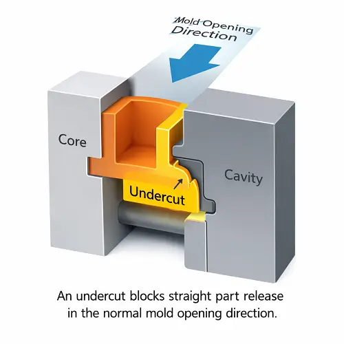
An undercut in injection molding is any feature that prevents the molded part from being released in the normal opening direction of the tool. If the part cannot move straight off the core or out of the cavity because a shape hooks behind the steel, that feature is an undercut.
In simple terms, the mold wants the part to move in one direction. The geometry says no.
That is why undercut injection molding is not just a shape problem. It is a release problem. The part may look easy to make until the mold opening direction is defined. Once the pull direction is set, the undercut becomes obvious. A side hole, a snap lip, an internal thread, or a recessed locking feature may all block straight ejection.
This is also where some confusion comes in between undercut mechanical design and molding design. In mechanical design, the undercut may be there for fit, locking, or assembly. In plastic molding, that same feature has to be evaluated through the mold. A useful part feature is not automatically a mold-friendly feature.
Why Injection Molding Undercuts Matter
Undercuts matter because they almost always increase tool complexity. A straight-pull mold is usually the simplest and most stable approach. Once undercuts enter the part, the mold may need side action injection molding, lifters, collapsible cores, hand-loaded inserts, or unscrewing mechanisms. Each option solves a release problem, but each option also adds moving steel, tighter timing, and more manufacturing risk.
The cost impact is not only in the initial tool quote. Injection molding undercuts can also affect cycle time, setup sensitivity, wear points, and maintenance frequency. A side action that has to travel every cycle introduces more moving parts than a straight shut-off. A lifter changes how the part ejects. An unscrewing mechanism for threaded geometry adds both mold complexity and processing time. These are manageable choices, but they should be deliberate.
A small side feature can look harmless on the screen, especially when the part itself is not large. In the tool, that same feature may widen the mold base, add fitting work, and create another moving component that has to stay aligned over thousands of cycles. That is usually where undercuts stop looking like a minor geometry detail and start looking like a tooling decision.
On some parts, the undercut also creates secondary molding risk. Deep side features can affect venting. Narrow recessed geometry can make packing less uniform. Local steel conditions become weaker. Fill behavior can change around the feature. The result is that the undercut is no longer just a release issue. It starts influencing the overall mold design.
Common Types of Undercuts in Plastic Molding
Undercut in plastic molding usually falls into a few common categories.
External undercuts are formed on the outside of the part. A snap hook, side slot, side hole, or locking tab often falls into this group. These are often handled with slides when the feature opens sideways relative to the main pull direction.
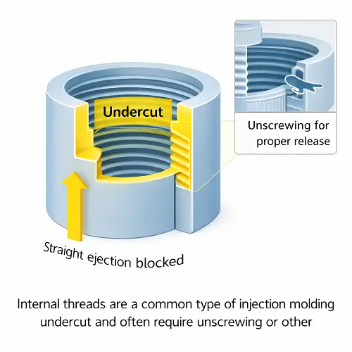
Internal undercuts are usually more difficult. Threads, internal retention beads, locking grooves, and recessed inside features can trap the core. These often require lifters, collapsible cores, or unscrewing motion depending on depth and geometry.
Some undercuts are small enough to redesign out of the part. Others are essential to product function and must stay. That is where undercut design becomes an engineering decision instead of a simple drafting correction.
A useful way to think about design undercuts is this: if a geometry helps the product but blocks simple release, the part has crossed from easy molding into managed molding. That does not make the design wrong. It just means the mold has to be designed around the feature instead of treating it like a standard wall.
Side Actions, Lifters, Shut-Offs, and Other Tooling Options
There is no single tooling solution for injection molding undercuts. The right method depends on geometry, pull direction, material, production volume, and how much complexity the project can tolerate.
A side action injection molding solution is one of the most common ways to form external undercuts. A slide moves sideways as the mold opens, releasing the trapped feature before the part ejects. This works well for side holes, windows, and external locks. It is reliable when designed well, but it adds steel movement, timing, and maintenance points.
Lifters are often used for smaller internal or angled undercuts. Instead of moving straight, the lifter travels upward and slightly inward or outward during ejection. This allows the feature to clear the undercut as the part leaves the mold. Lifters can be efficient, but the geometry has to cooperate. Deep or aggressive undercuts can overload the concept quickly.
This is also where teams sometimes get overly optimistic. A feature may look small enough for a lifter in CAD, but once the release angle, available travel, nearby ribs, and ejector layout are reviewed, the space disappears quickly. That is a common reason undercut solutions should be reviewed in section, not just in a shaded model.
Unscrewing tools are used for threaded parts that cannot flex off a core. This is where injection molding screw off slide draft discussions sometimes come up in design review. A thread form may look small on the model, but once the pitch, draft, and release path are studied, the team realizes the feature cannot be handled by ordinary ejection. A true screw-off mechanism may be the only stable answer.
Collapsible cores are another option for certain internal undercut designs, especially round features that need to release inward. These can be effective, but they are not a casual tooling choice. They are more specialized and should be justified by production value and part function.
Hand-loaded inserts can also solve an undercut on low-volume tools or prototype molds. This is not usually the best option for high-volume production, but it can make sense when the part quantity is modest and the geometry would otherwise force a much more expensive tool.
Shut-off injection molding strategies are sometimes able to eliminate a side action completely. A feature that looks like it needs a slide may sometimes be reworked into an injection molding shut off condition through parting-line changes and steel-to-steel sealing geometry. That is often one of the smartest ways to simplify a mold. Not every undercut can be turned into a shut-off, but when it can, the savings in cost and maintenance are real.
When a Shut-Off Can Replace an Undercut Mechanism
This is one of the best places to improve a design before tooling starts.
Some features that are called undercuts are not true undercuts once the parting line is moved and the mold opening strategy is reconsidered. A side notch, edge detail, or open window may look trapped in the first CAD layout, but after the parting direction changes, the feature can sometimes be formed with a clean shut-off instead of a slide.
That is why injection molding shut off design deserves real attention early in DFM. A good shut-off can remove an entire side action from the mold. It can also make the tool more compact, more stable, and easier to maintain. A bad shut-off, though, creates weak steel, flash risk, and alignment problems. The feature has to be reviewed through steel condition, sealing length, and wear resistance, not just through the part model.
In practice, many good undercut design decisions are actually parting-line decisions. The geometry does not always need to be simplified. Sometimes the mold layout just needs to be smarter.
When to Keep the Undercut and When to Design It Out
This is where real design judgment matters.
Some undercuts are worth keeping because they carry the product function. Snap retention, hidden locking, internal threading, or assembly geometry may be essential. If removing the undercut weakens the part or creates a worse assembly method, then the tooling solution is usually justified.
Other undercuts are just inherited geometry. A designer may add a recess, step, or side detail because it looks clean on the screen, without realizing it creates a slide, lifter, or complex shut-off. In those cases, the best answer is often to design the undercut out.
A good review asks a few simple questions. Does the undercut perform a real mechanical function? Can the same function be achieved with draft, a different split line, or a more open geometry? Does the undercut justify a side action when the tool volume is low? Will the undercut increase maintenance more than the product benefits from it?
This is why undercuts manufacturing decisions should not be made in isolation. Product design, mold design, and production goals all need to be in the same discussion.
Cost Impact of Injection Molding Undercuts
The biggest mistake is to treat an undercut as if it only adds a little machining. In reality, injection molding undercuts usually increase cost in several layers at once.
The first layer is tool construction. A straight-pull mold is simpler than a mold with slides, lifters, or unscrewing action. More moving parts mean more design time, more machining, more fitting, and more assembly work. In some tools, the mold may also require hydraulic or mechanical locking details, and in more complex systems this may involve an injection mold locking cylinder or another controlled movement to keep the action secure during molding.
The second layer is lead time. Every added mechanism introduces more design review, more steel work, and more fit-up. That can stretch mold delivery, especially on tools with multiple side features or internal release challenges.
The third layer is production behavior. A mold with side actions or lifters can run well, but it is rarely as simple as a straight-open tool. More mechanisms mean more wear surfaces, more alignment checks, and more maintenance over time. On higher-volume programs, this matters.
The fourth layer is part consistency. The undercut itself may be stable, but the tooling around it can influence ejection, cooling, venting, and steel durability. Some undercut-heavy parts are not difficult because they cannot be molded. They are difficult because they demand more control to keep running cleanly.
A small undercut on the part does not always mean a small impact on the tool. In real projects, the added cost often comes less from the shape itself and more from the motion, fit-up, timing, locking, and maintenance burden created around that shape. That is usually what customers underestimate when they first look at the model.
Design Tips for Handling Undercuts More Efficiently
The first rule is to confirm whether the feature is truly trapped. A lot of design undercut problems come from looking at the part before the pull direction is finalized. Once the correct opening direction is defined, some features stop being undercuts at all.
The second rule is to reduce the depth and severity of the undercut where possible. A small retention detail is easier to handle than a deep locking shape. If the function allows a shallower engagement, the tooling often becomes easier immediately.
The third rule is to study whether a shut-off can replace a moving action. A feature that can be formed by steel shut-off rather than a slide is often the better production choice.
The fourth rule is to think about draft and release around the undercut, not just the undercut itself. An undercut with poor neighboring draft can create a part that is technically released on one side but still difficult to eject overall. This is where undercut design and general plastic part design need to stay connected.
The fifth rule is to check the undercut against assembly tolerance and product function. A very aggressive mechanical lock may feel safe in design, but if it forces expensive tooling and difficult molding, the better product decision may be a modest change in geometry.
Common Mistakes in Undercut Injection Molding
One common mistake is assuming every undercut needs a slide. Some do, but others can be solved through shut-off strategy, parting-line changes, or a simpler design revision.
Another mistake is underestimating internal undercuts. External features are easy to see. Internal undercuts are easier to miss, especially in enclosed plastic parts. By the time they are noticed, the tooling concept may already be moving in the wrong direction.
A third mistake is approving the feature because the tool can technically be built, without checking whether it should be built that way. A mold can be made around a lot of difficult geometry. That does not mean the result is the best production tool.
This shows up often in prototype discussions. A feature may be accepted because a low-volume tool can work around it, sometimes with extra operator attention or a less efficient release method. Once the same part is pushed toward production, the undercut starts showing its real cost through slower cycling, added wear, or less forgiving setup behavior.
There is also occasional confusion between undercut machining and molded undercuts. In machining, an undercut may simply describe a local relief or groove created by a cutting process. In molding, the meaning is tied to mold release. The words overlap, but the manufacturing problem is different.
A Practical Comparison of Tooling Options
| Tooling option | Best use case | Main advantage | Main trade-off |
|---|---|---|---|
| Slide / side action | External side features, holes, windows | Reliable for many external undercuts | Higher tool cost and more moving steel |
| Lifter | Smaller internal or angled release features | Compact solution inside the mold | Limited by geometry and travel angle |
| Shut-off redesign | Open edge features and favorable parting lines | Can remove a mechanism entirely | Requires careful steel design |
| Unscrewing mechanism | Internal or external threads | Best for true threaded release | Expensive and slower |
| Collapsible core | Round internal undercuts | Solves trapped internal geometry | Specialized and costly |
| Hand-loaded insert | Low-volume or prototype molds | Lower upfront complexity in some cases | Not ideal for faster production |
Conclusion
Injection molding undercuts are not automatically bad, but they should never be treated casually. Every undercut changes the conversation from simple release to managed release. That affects mold layout, tooling options, maintenance, and cost.
The strongest projects are usually not the ones with no undercuts at all. They are the ones where the undercuts are intentional, justified, and supported by the right tooling plan. Some features should stay because the product needs them. Others should be redesigned before the mold becomes more complex than the part deserves.
That is why undercuts in injection molding are best reviewed early, while the geometry can still change and before the mold concept is frozen. A quick DFM review at that stage often saves far more time and money than fixing the tooling after steel has already been cut.
JeekMould supports plastic part design review, undercut analysis, mold building, and production for custom plastic parts. If a project includes side holes, snap features, internal locks, threads, or trapped geometry, send the CAD files before tooling release so the undercut strategy can be checked while the design is still flexible.
FAQs
What are injection molding undercuts?
Injection molding undercuts are features that prevent a part from being released in the normal mold opening direction. They trap the part behind the steel and usually require a different mold strategy.
Do all undercuts need side actions?
No. Some undercuts need slides or lifters, but others can be solved by moving the parting line, using a shut-off, or changing the geometry slightly.
What is side action injection molding?
Side action injection molding uses moving slides or similar mechanisms to form side features that cannot be released by straight mold opening.
Are undercuts always expensive?
Not always, but they usually increase tool cost compared with a straight-pull mold. The size of the cost increase depends on the feature type, quantity, and tooling method required.
What is the difference between an undercut in machining and an undercut in injection molding?
In machining, an undercut often means a relief groove or recessed cut made by a cutting tool. In injection molding, an undercut means a feature that blocks straight release from the mold.
Can a shut-off replace an undercut mechanism?
Sometimes yes. A good parting-line change or shut-off strategy can eliminate the need for a slide, but the steel condition has to be strong enough for stable production.