Bosses are small features, but they create a surprising number of molding and assembly problems when they are handled casually. In CAD, a boss looks harmless. It is usually just a cylindrical feature added to support a screw, align two parts, or hold a component off the base wall. In a molded part, that same feature affects local wall thickness, cooling, shrinkage, draft, screw stress, and often the cosmetic surface on the opposite side of the part. That is why injection molding boss design deserves more attention than it usually gets during early plastic part layout.
In plastic product design and development, bosses are used for very practical reasons. They provide fastening points, help position mating parts, create stand-off height for boards or internal components, and make internal assembly possible without extra hardware in the wrong places. None of that is optional on many products. The problem is that bosses are often designed as assembly features first and molding features second. A boss can look strong in section view, pass a quick design review, and still create sink, cracking, distortion, or poor screw retention once the mold starts running and the part goes into real assembly.
That is the real point of bosses in plastic design. A good boss is not just a thicker cylinder. A good boss is a balanced feature that molds cleanly, stays dimensionally stable, supports the fastening method, and does not damage the rest of the part. The best bosses design usually comes from control rather than excess.
Injection Molding Boss Design Guidelines
A few starting rules help keep boss geometry from becoming a problem too early. These are not hard standards for every part, but they are practical starting points for molded plastic parts that need internal fastening or support features.
| Design factor | Practical starting point |
|---|---|
| Boss wall thickness | Often around 40% to 60% of the nominal wall to help control sink |
| Draft angle | Usually 0.5° to 1° per side as a practical starting point |
| Base radius | Add a smooth fillet at the boss root to reduce stress concentration |
| Boss height | Keep unsupported height reasonable; tall bosses often need rib support |
| Screw bosses | Hole and outer diameter should match the actual screw type, resin, and assembly load |
| Spacing to outer walls | Leave enough distance so the boss does not print through the show surface too aggressively |
These guidelines matter because a boss is never just a local cylinder. It is attached to a floor, side wall, or internal platform, which means its geometry changes how the surrounding plastic behaves. A small electronics housing, a battery cover, and a larger structural plastic moulded enclosure may all use bosses, but they do not all tolerate the same proportions.
What Is a Boss in Injection Molding?
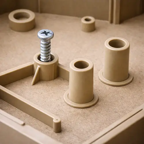
In injection molding, a boss is a raised cylindrical feature built into a plastic part to support fastening, alignment, spacing, or internal assembly. Most bosses are used to receive screws, support threaded inserts, guide mating components, or hold one internal part away from another at a controlled height. When people talk about a boss part feature, this is usually what they mean.
What makes a boss more important than it first appears is that it changes both assembly behavior and molding behavior at the same time. A boss may be there because the assembly needs it, but the mold still has to fill it, cool it, eject it, and hold it dimensionally. That is why a boss cannot be judged only by whether a screw fits. A boss that supports fastening but causes heavy sink on the outside wall is not really a good boss. A boss that looks solid but cracks during screw installation is not a good boss either.
The practical way to think about bosses in injection molding is simple: a boss is a functional feature that behaves like a local molding problem if the geometry is too heavy, too sharp, too tall, or poorly supported.
Common Types of Bosses in Plastic Design
Bosses design starts making more sense when the different job types are separated. Not every boss is there for the same reason, and the design logic changes depending on its function.
The most familiar type is the screw boss. Screw bosses are used to receive self-tapping screws, thread-forming screws, machine screws with inserts, or other threaded fastening methods. These show up in housings, covers, consumer products, appliances, automotive interior parts, and many electronic products. When someone searches for screw boss or screw bosses, this is almost always the feature they are talking about.
Another common type is the locating boss. A locating boss may not carry much fastening load, but it plays an important role in assembly by helping one part register against another. These bosses still need dimensional stability because poor alignment at a locating feature can affect the whole assembly.
Stand-off bosses are also common, especially in products that need controlled spacing inside the part. Circuit boards, covers, switch components, battery contacts, and internal mechanisms often rely on these bosses to sit at the right height above the base wall.
A useful distinction also exists between blind bosses and through bosses. A blind boss ends inside the part and usually contains a pilot hole or fastening hole that does not pass through the wall. A through boss continues through the wall and is open on both sides. Blind bosses are often easier to hide cosmetically, but they build local mass quickly. Through bosses can help in some layouts, but they can create sealing or packaging limitations.
Before deciding how thick or tall a boss should be, it helps to ask the most basic question first: what is this boss meant to do? A locating boss, a stand-off boss, and a screw boss should not all be designed exactly the same way.
Boss Wall Thickness Guidelines for Injection Molding
The most repeated boss mistake is still the same one: making the boss wall too thick because it is expected to carry load. That choice looks safe in CAD and often performs badly in molding.
As boss wall thickness increases, the boss starts behaving like a concentrated mass of plastic tied to a thinner surrounding wall. Cooling becomes uneven, local shrink becomes more visible, and sink marks become more likely, especially if the boss sits behind a cosmetic surface. The boss may feel stronger in the section view, but the rest of the part starts paying for that extra thickness.
That is why many engineers use a boss wall thickness around 40% to 60% of the nominal wall as a starting point. The point is not to treat that number as a fixed law. The point is to keep the boss from becoming a heavy lump that creates cosmetic read-through and unpredictable shrink behavior.
This matters even more in thin-wall housings, consumer products, and parts with visible outer surfaces. A boss can look harmless on the inside and still shadow through on the outside because the local plastic mass is too high. In real molded parts, a thick boss often becomes a cosmetic liability before it becomes a real strength advantage.
Screw Boss Design for Plastic Parts
Screw boss design is where boss geometry stops being a simple CAD feature and starts becoming a real engineering problem. A screw boss has to accept fastening load, resist local hoop stress, remain dimensionally stable, and still mold cleanly. That is a lot to ask from one small cylindrical feature.
The common failure pattern is familiar. The boss looks fine in the model, the first molded parts come out, and the problem only shows up during screw installation. The screw bites too hard, the boss root turns white, the upper section splits, or the retention torque drops after repeated use. At that point, the issue is not usually that the boss needed to be bigger. The issue is that the boss, the pilot hole, the screw type, the resin, and the support geometry were never balanced properly.
A self-tapping screw behaves differently from a machine screw with a brass insert. A thread-forming screw can create significant hoop stress. A resin that performs acceptably in one housing may crack at the boss when the same fastening geometry is used in a stiffer or more brittle plastic. That is why screw bosses should always be designed around the actual fastening method, not around outside diameter alone.
A screw boss that works well is rarely the fattest one. It is the one whose wall, hole, root, and support were designed for the real screw and the real load path.
Boss Height, Diameter, and Hole Size Guidelines
Boss height changes behavior faster than many designers expect. A short boss is usually easy to control. A tall boss becomes more sensitive to molding variation and more vulnerable under assembly load, especially when it stands without much lateral support.
As the boss gets taller, it becomes more likely to bend slightly during assembly, distort during cooling, or crack near the base under screw load. This gets worse when the boss is narrow and tall, or when the screw applies load near the upper section while the base remains unsupported.
Hole size matters just as much as outer diameter. If the pilot hole is too small, screw insertion stress rises quickly. If the hole is too large, screw retention drops. If the surrounding wall is too thin, the boss can split even when the first screw installation seems acceptable. That is why boss hole geometry should never be treated as an afterthought.
This is one of the reasons weak designs sometimes survive first assembly and still fail later. The boss may hold one time, but repeated installation, higher torque, or slightly different molding conditions can expose how little margin the feature actually had.

Draft Angle and Root Radius for Bosses
Draft is still necessary even when the boss sits inside the part and never touches the outside appearance. The inner bore grips the core, the outer wall still needs release, and a straight boss with no draft is simply asking the mold to work harder than it should.
A practical starting point is usually around 0.5° to 1° draft per side, adjusted for boss depth, resin, and finish requirements. Internal surfaces deserve real attention because the core side often sees more release pressure than people expect, especially on deeper bosses.
The boss root matters for a different reason. Many bosses fail at the base, not at the top. A sharp transition between the boss and the floor concentrates stress right where the load path changes. A smooth radius helps distribute that stress and improves both assembly durability and molding behavior.
This becomes especially obvious on cracked screw bosses. The upper section may still look acceptable, but the crack often begins at the base because the transition is too abrupt and the local stress has nowhere to go. Adding more wall thickness without improving the root shape usually moves the problem rather than solving it.
Rib Support for Injection Molding Bosses
Tall bosses often need rib support, especially when they carry screws or see repeated assembly loads. This is one of the most practical design decisions in injection molding bosses, and one of the most often delayed.
A rib-supported boss behaves better because the ribs stabilize the feature, reduce bending, and spread load into a wider section of the part. In most cases, this works better than simply making the boss wall thicker. Thick walls create sink and cooling imbalance. Proper rib support adds stiffness more efficiently.
A tall unsupported boss should usually raise suspicion. It may look fine in CAD, but once the molded part is assembled, that long unsupported cylinder often behaves less robustly than expected. A pair of well-placed ribs can do more for durability than a heavy wall ever will.
The same discipline still applies to the ribs themselves. Thick ribs can create their own sink and local mass problems. Good support geometry is controlled geometry, not just more material.
Boss Placement and Cosmetic Surface Risk
Bosses do not only create trouble through their own geometry. Placement matters too. A boss that sits too close to an outside wall can print through on the cosmetic surface even when the boss itself looks reasonable in section.
This is one of the most frustrating problems in plastic part design because the boss may work mechanically while the outer appearance still fails. The customer does not care that the internal feature is structurally sound if the visible wall shows read-through, sink, or a shadow mark.
Spacing helps. So does coring, balanced wall design, and avoiding unnecessary local mass. Bosses clustered in one area can also make the cosmetic side worse because the local plastic volume becomes too high and cooling becomes harder to control. The boss may not be “wrong” by itself. The problem may be that it sits too near a visible wall or too close to another heavy feature.
That is why boss placement should be reviewed through both assembly and appearance. Good boss design is not just the shape of the boss. It is also where the boss sits inside the housing.
Screw Bosses vs Insert Bosses
Not every fastening boss should use the same strategy. One of the most useful design decisions early in DFM is deciding whether a screw boss should take a direct screw or support a metal insert.
A direct screw boss is simpler and usually cheaper upfront. It avoids the extra insert component and the extra insert process. This works well for many plastic parts, especially when the part is not repeatedly disassembled and the loading is moderate.
An insert boss adds complexity, but it can improve repeatability and long-term thread durability, especially when the part will be assembled and disassembled multiple times. The design requirements also shift. Insert bosses need enough surrounding plastic to hold the insert securely without cracking, and they still need to be designed with molding behavior in mind.
The choice is not simply about which one feels stronger. It depends on how often the assembly will be opened, what torque is expected, what resin is being used, and how much risk the project can tolerate. A boss that works with a direct screw in one consumer product may need an insert in another application that sees repeated service access.
Cored Boss Design vs Overly Thick Bosses
A lot of weak boss design comes from the same instinct: if the boss needs strength, make it look more solid. In molded parts, that instinct often causes more harm than good.
A boss does not usually need to look like a thick solid pillar. In fact, that kind of geometry often creates more sink, worse cooling behavior, and more shrink distortion. A cored boss design is generally better because it reduces local mass while still giving the feature the structure it needs.
This is one of the most useful mindset changes in boss design for injection molding. A boss that looks heavier is not automatically a better boss. A boss that is cored properly, supported properly, and proportioned to the real load path usually performs better than an oversized thick cylinder.
In practical molding, thick-looking bosses often create the illusion of strength while quietly increasing risk. A cored boss is usually the more mature design.
Boss Performance Under Screw Torque and Repeated Assembly
A boss that survives one assembly cycle is not automatically a good boss. Real products often see repeated installation, service access, repair, or at least variation in assembly torque. That is where weak bosses start showing their true behavior.
Some bosses do not crack immediately. Instead, they begin whitening at the root, lose retention gradually, or show subtle deformation after repeated screw installation. In real production, those failures are often more expensive than obvious early cracks because they show up later, after the design was assumed to be safe.
Torque matters here. A boss that feels fine under one assembly condition may be overstressed when torque increases slightly or when operators use a different process window. This is especially important for screw bosses in housings and covers that may be opened and reassembled more than once.
That is why repeated assembly behavior deserves more attention in boss design. First-pass assembly success is not the same thing as long-term boss performance.
Common Boss Design Problems: Sink, Cracking, and Weak Screw Retention
Most boss-related failures repeat because the underlying causes repeat. Sink marks are one of the most common, especially when the boss creates too much local mass relative to the surrounding wall. On cosmetic housings, this alone can make the part unacceptable.
Cracking is another common issue, especially around screw bosses. Sometimes it happens during the first screw insertion. Sometimes it appears later after handling, torque application, or repeated assembly. The root cause is usually a mix of wrong pilot size, sharp root geometry, brittle material, excessive hoop stress, or weak support.
Weak screw retention is a different problem, but it often comes from the same design imbalance. The boss may not crack at all. It may simply fail to hold the screw well because the wall, hole, or material were not properly matched to the fastening method.
Boss distortion and hole out-of-round conditions also show up in real tools, especially when deep bosses are poorly cooled or unsupported. These problems affect fit and alignment before the screw is even installed.
These are not random defects. They usually come back to the same variables: wall thickness, geometry, placement, support, and fastening strategy.
Common Boss Design Mistakes in Plastic Parts
The first repeated mistake is using thickness as the main strength strategy. This often creates sink and cosmetic read-through without solving the real structural issue.
The second is treating a screw boss like a simple cylinder instead of a loaded feature. A screw boss should be designed around the real screw, the real hole, and the real material response.
The third is ignoring support. Tall bosses without ribs often look acceptable in section view and fail later under assembly load.
The fourth is forgetting that the boss is attached to a larger part. The surrounding floor, wall, and housing structure all change how the boss behaves in molding and in use.
The fifth is assuming the part is fine because the first molded samples assemble once. That is not proof of a robust design. Some weak bosses survive first assembly and only begin failing after repeated screw installation, drop testing, or longer production runs.
Conclusion
Bosses are small features with large consequences. In injection molding, they influence fastening strength, assembly accuracy, cosmetic quality, and long-term durability at the same time. That is why boss design should never be treated as a secondary detail.
The strongest boss designs usually come from balance, not bulk. Reasonable wall thickness, proper draft, smooth root radii, controlled placement, and rib support where needed will usually outperform an oversized boss that only looks strong in CAD. A screw boss that molds cleanly and survives real assembly is more valuable than a heavy boss that creates sink or cracking later.
If a plastic part depends on screw bosses, locating bosses, or other internal boss features, the best time to review them is before tooling release. JeekMould supports boss design review, mold design, and custom injection molding for plastic parts. You can upload your CAD files to JeekMould to request a quote and get early feedback on boss geometry, fastening strategy, and molding feasibility before steel is cut.
FAQs
What is a boss in injection molding?
In injection molding, a boss is a raised cylindrical feature built into a plastic part to support fastening, alignment, spacing, or assembly.
What are screw bosses?
Screw bosses are boss features designed to receive screws or support threaded fastening inside a plastic part.
What is a boss part in plastic design?
When people search for a boss part, they usually mean the molded boss feature inside a plastic part rather than a separate component.
What matters most in bosses design?
Wall thickness, hole size, draft, root radius, height, placement, and support all matter because a boss has to mold well and survive assembly at the same time.
Why do bosses crack after screw installation?
Boss cracking is often caused by excessive hoop stress, wrong pilot hole size, sharp root transitions, brittle material, or weak support at the base.
How do bosses fit into plastic product design and development?
In plastic product design and development, bosses are critical internal features because they affect assembly, structural behavior, molding quality, and long-term reliability all at once.