
Cooling time is often the part of the injection molding cycle that quietly controls the final part cost. Filling may finish quickly, and packing may only take a short part of the cycle, but the mold still has to stay closed until the plastic becomes stiff enough to eject without warping, sinking, or changing dimensions later.
Many molding problems start when cooling time is reduced too aggressively. A part may look acceptable when the mold opens, but the same part can bend, shrink around bosses, lose flatness, or fail assembly after sitting outside the tool. In those cases, the problem is not only cycle time. The real problem is uneven heat removal.
Reducing cooling time safely means looking at wall thickness, cooling channel design, coolant flow, mold temperature, packing stability, material shrinkage, and ejection behavior together. This article explains how to shorten injection molding cooling time without creating warpage or dimensional problems, and how to decide whether the issue should be solved through part design, mold design, process tuning, or advanced cooling methods such as conformal cooling.
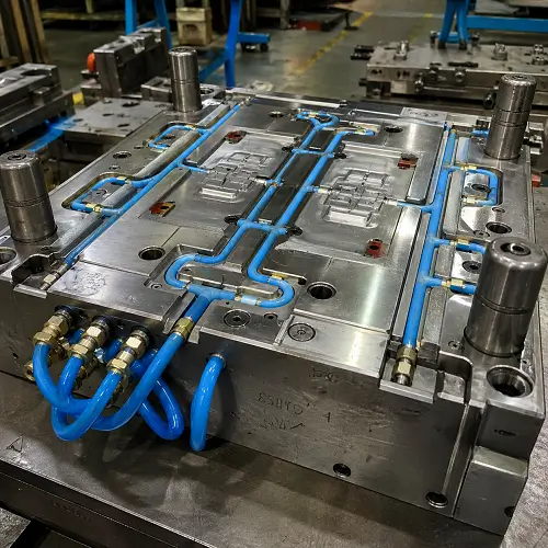
How Cooling Time Affects Injection Molding Cycle Time
Cooling time is usually the longest part of the injection molding cycle. Filling may only take a few seconds. Packing may also be short, depending on the material, gate size, and part geometry. Cooling often takes much longer because the molded part must become stiff enough to eject without bending, shrinking unevenly, sticking to the core, or changing shape after release.
That is why cooling time receives so much attention in injection molding production. A few seconds saved on each cycle can make a real difference when a mold runs thousands or millions of shots. Shorter cooling time can improve machine capacity, reduce part cost, and help production schedules. The problem is that cooling time cannot be reduced by guesswork. A molded part may look acceptable when the mold opens, but if the internal heat has not stabilized, the part can warp, shrink, twist, or lose critical dimensions after ejection.
A good cooling strategy is not just about making the mold colder. The real goal is to remove heat evenly and repeatably. The part needs to cool fast enough for production, but also evenly enough to hold its final shape. That balance depends on wall thickness, mold cooling layout, coolant flow, mold temperature, packing conditions, resin type, and ejection timing.
For many molded parts, cooling time reduction should begin during injection mold design rather than during production troubleshooting. Once the cooling channels are already drilled and the mold is built, the options become more limited and more expensive.
Why Cooling Time Cannot Be Reduced Blindly
Reducing the cooling timer on the molding machine may look like the fastest way to shorten cycle time. Sometimes that works for a simple part with generous tolerances. For precision parts, flat housings, clips, covers, optical parts, thick components, and assembly-critical parts, that approach can create hidden problems.
Plastic cools from the outside toward the inside. The surface of the part contacts the mold steel and loses heat first. The center of the wall cools more slowly. If a thick section is ejected too early, the outer skin may be firm while the inner core is still hot. After ejection, that remaining heat continues to move through the part. The plastic keeps shrinking outside the mold, and the final size may drift away from the inspection result taken immediately after molding.
This is one reason some molded parts pass early inspection but fail assembly later. The issue is not always the measuring tool or the molding operator. In many cases, the part was removed before the thermal and dimensional condition had stabilized enough for that geometry and material.
Uneven cooling makes the problem worse. If one side of the part cools faster than the other, shrinkage will not be balanced. The colder side may freeze earlier while the hotter side keeps contracting. That difference creates internal stress and shape change. The visible result may be warpage, twisting, sink marks, poor flatness, or mismatched assembly surfaces.
Cooling time should be reduced only after the mold, part design, and process can support the faster cycle.
Main Factors That Control Cooling Time
Cooling time is controlled by several variables working together. No single machine setting can fix a poor part design or a weak cooling layout.
| Factor | Effect on Cooling Time | Common Problem When Ignored |
|---|---|---|
| Wall thickness | Thick sections hold heat longer and cool slowly | Long cycle time, sink marks, voids |
| Cooling channel distance | Channels too far from the cavity remove heat slowly | Hot spots and uneven cooling |
| Cooling channel layout | Poor layout creates temperature differences across the part | Warpage and unstable dimensions |
| Mold temperature | Higher mold temperature may improve flow and surface quality but can extend cooling | Long cycle or soft ejection |
| Coolant flow | Weak flow reduces heat transfer from the mold | Slow cooling and unstable production |
| Material type | Semi-crystalline plastics often need controlled cooling | Shrinkage variation and warpage |
| Packing condition | Poor packing creates uneven density before cooling finishes | Sink, shrinkage, dimensional drift |
| Ejection timing | Early ejection shortens cycle but may deform the part | Ejector marks, bending, distortion |
A stable cooling process usually comes from improving several of these areas together. Reducing the cooling timer alone may create a faster cycle on paper, but that does not mean the molded part is production-ready.
Cooling Time Calculation: Why Wall Thickness Matters So Much
Cooling time is strongly connected to the thickest section of the molded part. Heat must travel from the center of the plastic wall to the mold surface before the part becomes stiff enough to eject. Because of that, cooling time does not increase in a simple straight line with wall thickness.
In practical molding work, cooling time often rises roughly with the square of the thickest wall section. That means a 4 mm wall does not cool only twice as slowly as a 2 mm wall. The thicker section may control the entire molding cycle, especially when that area is far from the cooling channel or located around a boss, rib intersection, thick corner, or deep core.
The exact cooling time depends on resin thermal behavior, melt temperature, mold temperature, ejection temperature, wall thickness, and cooling channel efficiency. Even so, wall thickness is usually the first place to check when a mold has a long cooling cycle.
| Part Condition | Cooling Risk | Practical Meaning |
|---|---|---|
| Thin and uniform walls | Lower risk | Cooling time can usually be optimized through process settings and standard cooling layout |
| Local thick bosses or pads | Medium to high risk | These areas may control the entire cooling cycle |
| Deep cores or thick corners | High risk | Special core cooling, baffles, bubblers, or insert changes may be needed |
| Thick semi-crystalline parts | High risk | Shrinkage and warpage must be checked carefully |
| Glass-filled parts with uneven flow | High risk | Fiber orientation and cooling balance both affect final shape |
This is why cooling time reduction should not start with the machine screen. The thickest plastic section often decides how fast the mold can safely run.
Start With Wall Thickness Before Adjusting the Machine
Wall thickness has a major effect on cooling time because heat must travel through the plastic before leaving through the mold steel. Thin, uniform walls cool quickly and predictably. Thick sections cool slowly and often become the reason the entire cycle cannot be shortened.
This is why heavy bosses, thick ribs, large pads, deep corners, and uneven wall transitions cause so many molding problems. These areas hold heat, shrink more, and often force the molder to keep a longer cycle even when most of the part is already cool enough.
The best way to reduce cooling time is often to remove unnecessary plastic mass. A thick mounting boss can sometimes be cored out. A heavy pad may be redesigned with ribs. A thick corner can often be softened with a smoother transition. A structural area may not need to be solid if rib design can provide enough stiffness.
Good wall thickness design also reduces injection molding defects. Sink marks, voids, warpage, and dimensional drift are often connected to thick or uneven sections. A part with balanced wall thickness is easier to cool, easier to pack, and easier to control in production.
Example: Why One Thick Boss Can Control the Whole Cycle
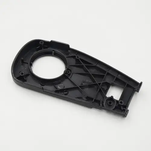
A common example is an electronic housing with a mostly thin outer wall but several thick screw bosses on the inside. The outside wall may cool quickly, but the boss base stays hot because the steel around that area cannot remove heat fast enough. If the mold opens too early, the housing may look acceptable at first and then show sink around the boss, slight distortion near the mounting area, or dimensional shift around the screw location.
In this type of part, lowering the mold temperature may not solve the real issue. The thick boss is still holding heat. A better correction may include coring the boss, reducing the boss base thickness, adding ribs for support, improving local cooling, or reviewing packing time before reducing cooling time.
This is why cooling time reduction often starts with part geometry rather than molding machine settings. A few seconds saved on the cycle will not help if the part later fails assembly because the boss area continues shrinking after ejection.
Improve Mold Cooling Design Instead of Only Lowering Mold Temperature
Lowering mold temperature can sometimes reduce cycle time, but this method has limits. A mold that runs too cold may cause poor surface finish, visible flow marks, higher molded-in stress, weak weld lines, or filling problems. The part may cool faster, but the quality may become unstable.
A better approach is to improve how heat leaves the mold. Cooling channel layout, channel diameter, channel distance from the cavity, flow balance, water temperature, and mold steel thickness all affect cooling performance.
Conventional cooling channels are usually drilled as straight holes. Straight drilled channels are simple, reliable, and cost-effective. For flat parts and simple mold inserts, conventional cooling often works well. The limitation appears when the molded part has a curved surface, deep cavity, tall core, thick local section, or complex geometry. A straight channel may sit far away from the cavity surface in the exact area where heat removal is most needed.
When the cooling channel is too far from the cavity, heat must travel through more steel before reaching the coolant. That slows cooling and creates hot spots. If one area of the mold stays hotter than another, the molded part will not shrink evenly.
A good injection mold cooling design places cooling where the heat actually needs to leave the part. The designer should review the cavity contour, core depth, part thickness, gate location, shrinkage behavior, and expected hot spots before deciding the cooling layout.
Use Conformal Cooling Where Conventional Cooling Cannot Reach
Conformal cooling can reduce cooling time when straight drilled channels cannot follow the shape of the molded part. A conformal cooling channel follows the cavity or core contour more closely, so heat does not need to travel as far through the steel before reaching the coolant.
This can be useful for deep cores, curved housings, thick part sections, tall ribs, medical components, complex automotive parts, and areas where conventional cooling leaves a local hot spot. The main value is not only faster cooling. The larger value is more uniform cooling. When the part cools evenly, shrinkage becomes easier to control, and the risk of warpage is lower.
Conformal cooling is not the right answer for every mold. It can increase tooling cost, require additive manufacturing or hybrid insert construction, and create design concerns around channel strength, cleaning, water flow, and long-term durability. A poorly designed conformal cooling insert can create new problems instead of solving old ones.
The best use of conformal cooling is selective and practical. If conventional drilled cooling can control the part well, there is no reason to make the mold more expensive. If the part has a known hot spot or deep geometry that standard cooling cannot reach, conformal cooling in that insert may be worth reviewing before tooling release.
Control Coolant Flow, Not Just Coolant Temperature
A mold cooling system needs enough flow to carry heat away from the mold. A low chiller setting does not help much if the coolant flow is weak, blocked, or poorly balanced.
In production, flow restrictions are common. Cooling channels may develop scale. Hoses may be too long or too small. Manifolds may be unbalanced. One circuit may receive strong flow while another circuit receives very little. The chiller display may show the correct temperature, but the actual mold temperature can still vary from one section to another.
Each cooling circuit should be checked for flow rate and temperature difference. If the coolant enters cold but leaves much warmer, the circuit may be removing a lot of heat, but the flow may not be high enough to keep temperature stable. If the flow is too low, heat transfer becomes weaker and the mold may slowly drift hotter during production.
Cooling stability matters because injection molding is a repeated thermal cycle. Every shot adds heat to the mold. Every cooling circuit removes heat. If those two actions are not balanced, the mold temperature changes over time. A process that looks stable for the first few shots may become unstable after the tool reaches full production temperature.
Reducing cooling time should always include a basic cooling system check. The mold may not need a major redesign if the real issue is blocked channels, weak flow, poor hose routing, or unbalanced water circuits.
Reduce Hot Spots in Thick or Hard-to-Cool Areas
Hot spots often control the entire molding cycle. Most of the part may be cool enough to eject, but one thick boss, deep core, or heavy rib intersection may still be too hot. The mold then has to stay closed longer because of that one area.
Common hot spot locations include thick wall transitions, large bosses, rib intersections, deep cores, closed-end holes, thick corners, and areas far from cooling channels. These areas hold heat longer than the surrounding plastic and often create sink marks or local shrinkage.
Several methods can reduce hot spots. The part can be redesigned with more uniform wall thickness. The mold can use closer cooling channels, baffles, bubblers, high-conductivity inserts, improved core cooling, or conformal cooling. The gate and packing process can also help reduce sink and shrinkage in these areas.
| Method | Best Used For | Limitation |
|---|---|---|
| Wall thickness reduction | Thick sections, heavy bosses, large pads | Requires part design change |
| Better conventional cooling layout | Simple or moderately complex molds | Limited by straight drilling access |
| Baffles and bubblers | Deep cores and localized hot spots | Need proper flow and maintenance |
| High-conductivity inserts | Local hot areas around cores or thick sections | Material and insert cost may increase |
| Conformal cooling | Complex contours and hard-to-reach hot spots | Higher tooling cost and design complexity |
| Packing optimization | Sink, shrinkage, density variation | Cannot fully fix poor cooling or poor geometry |
The right solution depends on the part. A simple thick boss may only need better coring and rib design. A deep core may need a bubbler or baffle. A complex contour may justify conformal cooling. A high-volume mold may justify more expensive cooling improvements because every second saved affects long-term production cost.
This is where cooling time connects directly with injection molding cost. A faster cycle can reduce unit cost, but only if the faster process still produces stable parts. Scrap, rework, and dimensional problems can erase any cycle time saving.
Balance Packing Before Shortening Cooling Time
Cooling problems are not always caused by cooling alone. Packing pressure, packing time, gate size, and gate freeze also affect how the part behaves during cooling.
During packing, additional molten plastic enters the cavity to compensate for shrinkage. If the gate freezes too early, the cavity can no longer receive material. Thick areas may continue shrinking without enough pressure compensation. The result may be sink marks, voids, or dimensional variation.
If cooling time is reduced before packing is stable, the part may become even less predictable. The molded part may leave the tool with uneven density. One area may be packed tightly while another area is under-packed. As the part cools and shrinks outside the mold, those density differences can turn into warpage or size changes.
Before cutting cooling time, the process should confirm that the gate freeze time is understood and the packing profile is not masking another issue. This is especially important for parts with thick bosses, cosmetic surfaces, large flat areas, or tight assembly dimensions.
A well-packed part cools more predictably. A poorly packed part may not become stable no matter how much the cooling timer is adjusted.
Watch for Warpage During Cooling Time Reduction
Warpage is one of the most common risks when cooling time is shortened. A part may look acceptable at ejection, then bend after sitting on the table. This happens because heat, shrinkage, and molded-in stress continue changing after the part leaves the mold.
Warpage in injection molding usually comes from uneven shrinkage. Uneven shrinkage can be caused by uneven cooling, non-uniform wall thickness, unbalanced filling, poor packing, fiber orientation, or early ejection. Cooling time reduction can expose these problems quickly because the part has less time to stabilize in the mold.
Flat covers, long housings, thin panels, battery cases, electronic enclosures, clips, and glass-filled parts are especially sensitive. These parts may need more careful cooling control because small temperature differences can create visible shape change.
A proper cooling time trial should not only check surface appearance. The team should measure flatness, hole position, mating surfaces, clip fit, part weight, and critical dimensions after the part has reached a stable room-temperature condition. For some materials, immediate measurement after molding does not represent the final part size.
Reducing cooling time is successful only when the part remains stable after ejection, not just when the machine cycle becomes shorter.
Consider the Plastic Material Before Setting a Cooling Target
Different materials need different cooling strategies. Amorphous plastics such as ABS, PC, PMMA, and PS usually behave differently from semi-crystalline plastics such as PP, PE, PA, POM, and PBT. Semi-crystalline materials often show higher shrinkage and stronger sensitivity to mold temperature and cooling rate.
Glass-filled plastics require extra attention. Glass fibers improve stiffness and reduce overall shrinkage in some directions, but fiber orientation can create directional shrinkage. A glass-filled nylon housing may warp even when the cycle time looks reasonable because the material shrinks differently along the flow direction and across the flow direction.
Optical parts and clear materials also need careful cooling. A mold that runs too cold may create stress, poor surface quality, haze, or optical distortion. In these cases, shorter cooling time may not be the main goal. Stable cooling and low stress may be more important than the fastest possible cycle.
The material data sheet gives a starting point, but the final cooling target must match the real part geometry and quality requirements. A simple PP cap and a flat PC housing do not need the same cooling strategy. A thick POM gear and a thin ABS cover should not be treated the same way.
Review Ejection Before Reducing Cooling Time
A molded part must be stiff enough to release from the mold cleanly. If the part is ejected too early, it may bend around ejector pins, drag on the core, stick in the cavity, or deform near ribs and bosses.
Some ejection problems are caused by cooling time, but others are caused by part design or mold design. Poor draft angle, deep ribs, rough texture, undercuts, sharp transitions, weak ejector layout, and high core grip can all make the part harder to release. When release is difficult, the molder may be forced to use a longer cooling time just to give the part more stiffness before ejection.
This means draft angle and ejection design can affect cycle time indirectly. A part with good draft, balanced ribs, proper surface finish, and well-placed ejector pins may eject safely at a shorter cooling time. A part with poor release conditions may need more cooling time even if the actual heat removal is acceptable.
Cooling time reduction should always include ejection review. The goal is not only to open the mold sooner. The goal is to eject the part without distortion, drag marks, whitening, ejector stress, or dimensional change.
A Practical Troubleshooting Order for Long Cooling Time
When cooling time is too long, the first step is not to cut the cooling timer. A safer troubleshooting order helps separate a true cooling issue from a part design issue, a water flow issue, a packing issue, or an ejection issue.
Start with the thickest wall section. If one area is much thicker than the rest of the part, that area may be controlling the whole cycle. Then check for visible signs such as sink marks, voids, late shrinkage, or local warpage. These defects often point to thick plastic, poor packing, or weak local cooling.
Next, check the mold temperature across critical areas. A mold may not be cooling evenly even when the chiller setting looks correct. Then check coolant flow rate, circuit balance, hose routing, and possible channel blockage. After that, review gate freeze and packing stability. If the gate freezes too early or packing is inconsistent, the part may continue shrinking unevenly after ejection.
Only after these checks should cooling time be reduced step by step. Each reduction should be verified by measuring part quality after stabilization, not only immediately after ejection.
| Step | What to Check | Why It Matters |
|---|---|---|
| 1 | Thickest wall and local hot spots | These areas often control the cooling cycle |
| 2 | Sink, voids, late shrinkage, or warpage | Defects show where heat and shrinkage are not controlled |
| 3 | Mold temperature across critical areas | Uneven mold temperature causes uneven shrinkage |
| 4 | Coolant flow and circuit balance | Poor flow limits heat removal |
| 5 | Gate freeze and packing condition | Poor packing creates density and shrinkage variation |
| 6 | Ejection behavior | Early ejection can bend or mark soft parts |
| 7 | Stabilized dimensions and assembly fit | Final part quality matters more than immediate appearance |
This order keeps the process grounded. It also prevents a common mistake: blaming cooling time when the real problem is wall thickness, packing, water flow, or poor release from the mold.
Use Moldflow or Thermal Simulation for Complex Parts
For complex or high-value molds, simulation can help identify cooling problems before steel is cut. Moldflow analysis can show filling behavior, pressure distribution, gate freeze, temperature differences, shrinkage risk, and warpage tendency. Thermal simulation can also help locate hot spots and compare different cooling layouts.
Simulation does not replace mold design experience. The result still depends on correct material data, realistic processing assumptions, and practical tooling judgment. However, simulation can reveal problems that may not be obvious from the CAD model alone.
This is especially useful for parts with thick and thin transitions, deep cores, long flow lengths, glass-filled materials, tight flatness requirements, or high annual production volume. If the tool is expensive and the production volume is high, finding a cooling issue before tooling can save far more money than correcting the mold later.
Simulation can also help decide whether conventional cooling is enough or whether conformal cooling, baffles, bubblers, or local insert changes should be considered.
Practical Ways to Reduce Cooling Time in Injection Molding
The most reliable way to reduce cooling time is to improve the full molding system instead of chasing one setting. In real production, several small improvements often produce a safer result than one aggressive change.
A practical cooling time reduction plan usually starts with part geometry. Thick sections should be reviewed first. Bosses, ribs, pads, corners, and wall transitions should be checked for unnecessary mass. If the part can cool more evenly by design, the mold does not need to fight the geometry as hard.
Next, the cooling channel layout should be reviewed. Channels should be close enough to remove heat efficiently but not so close that mold strength or durability is compromised. Deep cores and local hot spots may need special cooling features. The cooling circuits should be balanced so one area does not run much hotter than another.
The coolant system should also be checked. Flow rate, water temperature, hose layout, manifold balance, and channel cleanliness all matter. A mold with poor water flow will not cool well even if the channel layout looks good on the drawing.
The molding process should then be optimized carefully. Packing pressure, packing time, mold temperature, melt temperature, screw recovery, and ejection timing all affect the final result. Cooling time should be reduced step by step while checking part quality after stabilization.
For existing molds, the options may be more limited. Cleaning cooling channels, improving water flow, balancing circuits, adjusting process conditions, and correcting ejection issues may help. For new molds, the cooling strategy should be reviewed before mold manufacturing because better channel placement and insert design are much easier at that stage.
How JeekMould Reviews Cooling Time Before Tooling
JeekMould reviews cooling time as part of injection mold design and DFM, not just as a machine setting after sampling. The review starts with part geometry, wall thickness, material behavior, expected shrinkage, gate location, parting line, cavity layout, and areas where heat may be difficult to remove.
For parts with thick sections, deep cores, flatness requirements, cosmetic surfaces, or high production volume, cooling design needs extra attention. Conventional drilled cooling may be enough for some molds. Other molds may need baffles, bubblers, high-conductivity inserts, improved water circuit layout, or conformal cooling in selected areas.
The goal is not to build the most complicated mold. The goal is to build a mold that cools efficiently, ejects cleanly, and produces stable parts over real production runs. A slightly more thoughtful cooling design before tooling can prevent long cycle time, warpage, sink marks, and expensive mold corrections later.
If a molded part has thick walls, uneven shrinkage risk, warpage concerns, or a strict unit cost target, JeekMould can review the CAD model, material, part structure, and mold cooling concept before tooling release. Upload CAD files for mold design evaluation and injection molding quotation.