
Clamping force is one of the first items that should be checked before an injection mold is built. The molding machine has to keep the mold closed while molten plastic is injected into the cavity. If the machine does not have enough force to hold the mold shut, the part can flash at the parting line, dimensions can drift, and the molding process may become unstable.
Most customers do not need to calculate every molding parameter by themselves. They do, however, need to understand why machine tonnage matters. A large plastic part, a multi-cavity mold, a thin-wall housing, or a high-pressure material can require more clamping force than expected. If that review happens after the mold is finished, the project may run into machine fit problems, cost changes, or tooling adjustments.
Injection molding clamping force connects part size, projected area, material behavior, mold layout, cavity count, injection pressure, machine size, and production cost. This article explains how clamping force is estimated, what numbers are commonly used, what can go wrong when tonnage is too low or too high, and how JeekMould reviews machine capacity before mold manufacturing.
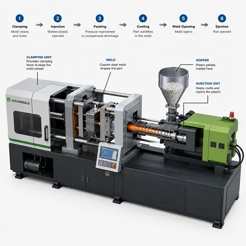
What Is Clamping Force in Injection Molding?
Clamping force is the force used by the injection molding machine to keep the mold closed during filling and packing. During injection, molten plastic enters the mold cavity under high pressure. That pressure pushes against the cavity surface and tries to open the mold along the parting line.
The clamp unit resists that opening force. If the clamp force is strong enough, the mold stays closed and the plastic fills the cavity properly. If clamp force is too low, the mold may open slightly. Even a small opening can create flash, parting line mismatch, unstable dimensions, or cosmetic defects.
Clamping force is usually described in tons. A 200-ton injection molding machine, for example, can apply about 200 tons of clamping force. Larger molded parts or larger mold layouts require higher tonnage because the injection pressure acts across a larger projected area.
Why Machine Tonnage Matters Before Mold Manufacturing
Machine tonnage should be reviewed before tooling because the mold has to match a real molding machine. Required clamping force affects more than whether the mold can stay closed. It also affects platen size, tie-bar spacing, mold height, shot capacity, injection pressure capability, machine availability, and production cost.
A mold can be correct from a cavity design standpoint and still be a poor fit for the selected press. The machine may not have enough clamping force. The mold base may not fit between the tie bars. The platen may be too small. The shot size may not be enough for the part and runner system. The process may also run too close to the machine limit, leaving little room for material or process variation.
Tonnage review belongs in the early DFM stage, before the mold layout and press selection are locked in. The team should check part size, projected area, cavity count, runner layout, material, expected pressure, and mold base size before steel is cut.
Injection Molding Clamping Force Formula
The basic calculation is simple:
Clamping Force = Projected Area × Cavity Pressure × Safety Factor
For early quoting and machine tonnage estimates, many molders use a clamp factor method:
Required Tonnage = Projected Area (in²) × Clamp Factor (tons/in²) × Safety Factor
Projected area is the area of the molded part and runner system viewed from the clamping direction. Clamp factor is an estimated pressure demand expressed as tons per square inch. The safety factor gives extra margin for material behavior, flow length, gate design, pressure variation, and normal production changes.
A pressure-based version can also be written like this:
Required Clamp Force (lb) = Projected Area (in²) × Cavity Pressure (psi)
Required Tonnage = Required Clamp Force (lb) ÷ 2,000
For most customers, the clamp factor method is easier to understand. Detailed pressure estimates can be refined later based on material, wall thickness, flow length, gate design, and mold filling behavior.
How to Calculate Projected Area for Injection Molding
Projected area is not the total surface area of the part. It is the area seen when looking at the molded part from the mold opening and closing direction. A simple way to think about it is the “shadow” of the part on the parting plane.
For a flat rectangular cover, projected area is close to length multiplied by width. For a round part, projected area is based on the circular outline. For a complex housing, the full outer profile in the clamp direction should be considered.
The runner system may also need to be included, especially in cold runner molds. If the mold has multiple cavities, the projected area of all cavities must be added together. A four-cavity mold does not use the projected area of one part. The total projected area includes four parts plus runners, gates, and sometimes overflow or other molded features.
For early estimation:
Total Projected Area = Part Projected Area × Number of Cavities + Runner Projected Area
Multi-cavity mold design can increase required machine tonnage quickly. The part itself may be small, but once several cavities and runners are added, the mold may need a much larger press.
What Clamp Factor Should Be Used for Tonnage Calculation?
The clamp factor depends on the material, part geometry, wall thickness, flow length, gate design, and pressure needed to fill the cavity. There is no single number that fits every injection molding project.
For early estimating, these ranges are practical starting points:
| Part or Material Condition | Rough Clamp Factor |
|---|---|
| Easy-flow materials and simple parts | 2 to 3 tons/in² |
| General-purpose molded parts | 3 to 4 tons/in² |
| Higher-pressure materials or tighter parts | 4 to 5 tons/in² |
| Thin-wall, long-flow, glass-filled, or difficult parts | 5 to 7 tons/in² |
These values are not final engineering guarantees. A simple PP cover may not need the same clamp factor as a thin-wall PC housing or a glass-filled nylon structural part. Final machine selection should consider resin viscosity, wall thickness, flow length, gate size, cavity layout, venting, cosmetic requirements, and actual molding conditions.
A good supplier should not use one fixed number for every quote. The right tonnage estimate comes from the part and mold design.
Quick Tonnage Estimate Table
The table below shows how projected area can affect estimated machine tonnage when using a general clamp factor of 4 tons/in² and a 1.1 safety factor.
| Total Projected Area | Clamp Factor | Safety Factor | Estimated Tonnage |
|---|---|---|---|
| 20 in² | 4 tons/in² | 1.1 | 88 tons |
| 50 in² | 4 tons/in² | 1.1 | 220 tons |
| 100 in² | 4 tons/in² | 1.1 | 440 tons |
| 200 in² | 4 tons/in² | 1.1 | 880 tons |
| 400 in² | 4 tons/in² | 1.1 | 1,760 tons |
This table is only a rough early estimate. Final press selection should also check mold size, tie-bar spacing, shot capacity, material behavior, wall thickness, runner design, and the required process window.
The table also explains why large plastic parts need to be reviewed carefully before tooling. A wide projected area can push a project into large-tonnage equipment even when the part does not look especially heavy.
Example: Clamping Force Calculation for a Plastic Part
Here is a simple example using the clamp factor method.
| Item | Value |
|---|---|
| Projected area | 40 in² |
| Clamp factor | 4 tons/in² |
| Safety factor | 1.1 |
Required Tonnage = 40 × 4 × 1.1 = 176 tons
A calculated result of 176 tons does not mean the mold should always run on a machine exactly at 176 tons. In real production, a molder may choose a 180-ton or 200-ton machine depending on platen size, tie-bar spacing, mold height, shot size, material behavior, and process window.
The calculation gives a starting point. Machine selection still needs engineering judgment.
Multi-Cavity Mold Example: How Cavity Count Changes Required Tonnage
Multi-cavity molds often need more clamping force because the total projected area increases. This is easy to miss when a customer only looks at one part.
| Item | Value |
|---|---|
| Single part projected area | 12 in² |
| Number of cavities | 4 |
| Runner projected area | 8 in² |
| Total projected area | 12 × 4 + 8 = 56 in² |
| Clamp factor | 4 tons/in² |
| Safety factor | 1.1 |
Required Tonnage = 56 × 4 × 1.1 = 246.4 tons
In this case, a 250-ton machine may look close on paper, but the mold designer still needs to check more than tonnage. The machine must also fit the mold base, provide enough shot capacity, support the required injection pressure, and leave a stable process window.
Cavity count is not only a tooling cost decision. It also affects machine size, production planning, and long-term part cost.
What Happens If Clamping Force Is Too Low?
When clamping force is too low, the mold can open slightly during injection or packing. The most common result is flash. Flash appears as thin unwanted plastic along the parting line, around inserts, near shutoffs, or around vents.
Low clamping force can also create unstable dimensions. If the mold opens slightly under pressure, the cavity condition changes from shot to shot. The part may look acceptable in one cycle and show flash or thickness variation in the next. Inspection and assembly become less predictable.
In more serious cases, low tonnage can damage the mold. Repeated parting line separation under pressure can wear shutoff surfaces, stress guide components, and create long-term maintenance issues. What starts as a small quality issue can turn into a tooling problem if production continues without correction.
Clamping force calculation protects both part quality and mold life.
Can Too Much Clamping Force Cause Problems?
Higher clamping force is not always better. A machine with far more tonnage than needed may still produce parts, but excessive clamping force can create other problems.
Too much clamp force can reduce vent effectiveness because the parting line and vent surfaces are compressed more tightly. Poor venting can trap air in the cavity, leading to burn marks, short shots, poor filling, or cosmetic defects. Excessive clamp force can also increase mold wear, energy use, and machine load.
There is also a cost issue. A larger machine usually costs more to run. If a part can be molded safely on a smaller press with a stable process window, using an oversized machine may not be the most efficient production choice.
The goal is not to use the largest press available. The goal is to choose a machine that provides enough clamp force, enough platen space, enough shot capacity, and enough process stability without unnecessary cost.
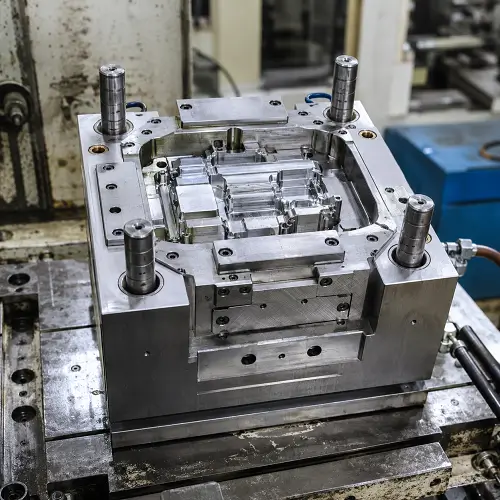
How Material, Wall Thickness, and Flow Length Affect Required Tonnage
The same projected area can require different clamping force depending on the material and part design. A low-viscosity material with a short flow path may fill at lower pressure. A high-viscosity material, thin-wall design, long flow length, small gate, or glass-filled resin may require higher injection pressure and a higher clamp factor.
Thin-wall parts often need more pressure because the melt must fill the cavity quickly before the flow front freezes. Long, narrow flow paths also increase pressure demand. Glass-filled materials may improve stiffness, but they can increase flow resistance and create directional shrinkage concerns.
Thick-wall parts do not always require the highest clamp factor, but they bring other issues. They may need longer packing and cooling time. They may be more sensitive to sink marks, voids, and dimensional drift. For thick sections, tonnage is only one part of the review. Packing, cooling, shrinkage, and ejection stability still need attention.
Clamping force should be reviewed together with wall thickness, material selection, gate design, flow length, and cooling strategy.
Clamping Force, Mold Size, and Machine Selection
A molding machine is selected by more than clamping force. The machine must physically accept the mold and provide enough injection capacity for the part and runner system.
| Machine Selection Item | Why It Matters |
|---|---|
| Clamping force | Keeps the mold closed during injection and packing |
| Platen size | Supports the mold base properly |
| Tie-bar spacing | Determines whether the mold can physically fit into the press |
| Mold height range | Confirms whether the mold can open, close, and run safely |
| Shot capacity | Ensures enough material volume for the part and runner |
| Injection pressure | Confirms the machine can fill the part under real conditions |
| Ejector stroke and pattern | Helps confirm part release and mold compatibility |
A mold can have the correct calculated tonnage and still be a poor fit for a specific machine. A wide mold base may need a larger press because of tie-bar spacing, even if the clamp force calculation looks moderate. A large part with a deep draw may also require enough opening stroke for safe part removal.
Machine selection should be checked with the mold design, not after the mold is complete.
How Clamping Force Affects Mold Cost and Production Planning
Clamping force affects production cost because machine size affects hourly rate, availability, energy use, and production planning. A part that requires a larger press may cost more to mold than a similar part that can run on a smaller machine.
Cavity count also affects the calculation. A multi-cavity mold can reduce part cost by producing more parts per cycle, but it also increases projected area and may require a larger machine. A larger machine may increase operating cost. The best mold layout is not always the one with the highest cavity count. The right choice depends on annual volume, part size, material cost, cycle time, machine availability, and tooling budget.
Clamping force also matters during quoting. If a supplier understands the required tonnage early, the quotation can reflect the real molding setup. If the tonnage is underestimated, the project may face cost changes, mold modification, or machine scheduling problems later.
Common Mistakes in Injection Molding Tonnage Calculation
One common mistake is using part weight instead of projected area. Part weight matters for shot size and material usage, but clamping force is mainly driven by projected area and pressure.
Another mistake is forgetting the runner area. In a cold runner mold, the runner system also sees pressure and contributes to projected area. This becomes more important in larger layouts or multi-cavity molds.
Some customers also confuse machine injection pressure with cavity pressure. These values are related, but they are not the same. Pressure is lost through the barrel, nozzle, runner, gate, and flow path before the plastic reaches every area of the cavity. For tonnage estimating, the useful value is the pressure acting inside the mold cavity, or a practical clamp factor based on molding experience.
A fourth mistake is not adding a safety factor. Running a mold right at the calculated clamp limit leaves little room for material variation, process adjustment, pressure spikes, or production changes. A modest safety factor helps protect the process window.
The final mistake is choosing the machine after the mold design is already fixed. Machine fit, tonnage, mold size, shot capacity, and production planning should be checked before tooling starts.
What Information Helps Estimate Machine Tonnage?
Customers do not need to send a completed mold design to estimate clamping force. A few basic project details are usually enough for an early review.
Useful information includes CAD files or 2D drawings, overall part dimensions, material choice, expected annual volume, target cavity count, part weight if available, surface or cosmetic requirements, tolerance requirements, and whether a hot runner or cold runner system is expected.
If the cavity count is not decided yet, that is also fine. The mold layout can be reviewed based on part size, projected area, production volume, and cost target. In many projects, the right cavity count is decided after balancing tooling cost, cycle time, machine tonnage, and annual demand.
For large parts, flat housings, wide covers, thick structural parts, or multi-cavity molds, early tonnage review can prevent a common problem: designing a mold that looks reasonable in CAD but does not fit the best available molding machine.
How JeekMould Reviews Machine Tonnage Before Tooling
JeekMould reviews machine tonnage before mold manufacturing starts. The team checks projected area, material, wall thickness, gate layout, runner system, cavity count, expected molding pressure, mold base size, and machine fit. This early review helps prevent problems such as insufficient clamping force, limited platen space, tight tie-bar clearance, low shot capacity, or a narrow process window.
JeekMould supports injection molding projects from small precision plastic parts to larger molded components, with injection molding machines available up to 1,980 tons of clamping force. This machine range allows JeekMould to match mold and part requirements with a suitable press instead of forcing every project into one machine size.
For customers, the question is not only whether the plastic part can be molded. The more important question is whether the mold, part design, material, and selected machine can run together in stable production. JeekMould reviews those details during the DFM and quotation stage so tooling decisions are based on real production requirements.
If a plastic part has a large projected area, multiple cavities, thick sections, or uncertain machine tonnage requirements, CAD files can be reviewed before tooling. JeekMould can evaluate clamping force, mold design, machine fit, and injection molding quotation before mold manufacturing begins.
Conclusion
Injection molding clamping force is more than a simple formula. It is an early engineering check that helps confirm whether the mold, part design, material, and molding machine can work together in stable production.
The basic calculation starts with projected area, clamp factor, and safety factor. From there, the review should also consider material behavior, wall thickness, flow length, gate design, runner layout, cavity count, mold base size, shot capacity, and machine fit. A correct tonnage estimate helps avoid flash, unstable dimensions, oversized machine cost, and tooling changes after mold manufacturing.
Machine tonnage should be reviewed before tooling begins, especially for large parts, multi-cavity molds, or parts with uncertain projected area. Upload your CAD files to JeekMould for clamping force review, mold layout evaluation, and injection molding quotation before mold manufacturing starts.
FAQs
How do you calculate clamping force in injection molding?
Clamping force can be estimated by multiplying projected area by a clamp factor and a safety factor. A practical formula is: Required Tonnage = Projected Area (in²) × Clamp Factor (tons/in²) × Safety Factor. The final value should also be checked against material, wall thickness, cavity count, runner layout, and machine fit.
What is projected area in injection molding?
Projected area is the area of the part and runner system viewed from the mold opening direction. It is not the full surface area of the part. For multi-cavity molds, the projected area of all cavities and runners should be included in the clamping force calculation.
What happens if injection molding tonnage is too low?
If tonnage is too low, the mold may open slightly during injection or packing. This can cause flash, unstable dimensions, poor repeatability, cosmetic defects, and possible mold wear at the parting line or shutoff areas.
Is higher clamping force always better?
No. Excessive clamping force can reduce venting effectiveness, increase mold wear, use more energy, and raise production cost. The best machine is not always the largest machine. The right press should provide enough clamping force, machine fit, shot capacity, and process stability.
What information is needed to estimate machine tonnage?
CAD files or 2D drawings are the best starting point. Material, overall part size, expected cavity count, runner type, annual volume, cosmetic requirements, and tolerance requirements also help the molding team estimate projected area, clamp factor, mold size, and suitable machine tonnage.