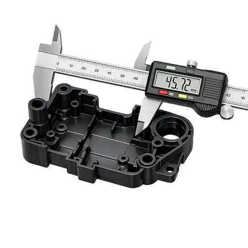
Tolerance becomes a real issue as soon as a plastic part moves from CAD to production. A dimension may look reasonable on the drawing, but molded plastic does not behave like machined metal. The final part changes during filling, packing, cooling, shrinkage, and ejection, and those changes do not affect every resin or every feature in the same way.
That is why a small ABS housing, a PP lid, and a glass-filled nylon bracket cannot be judged by the same tolerance logic. Some parts hold size well. Some parts look fine in the first sample but drift when production starts. Some features are easy to control, while others create problems long before the mold itself is questioned.
The real question is not whether a supplier can make one sample measure correctly. The real question is what tolerance range is realistic for stable production. That depends on part size, material behavior, wall thickness, feature type, and whether the critical dimensions are being molded directly or finished afterward.
What injection molding tolerance really means
Injection molding tolerance is the allowable difference between the nominal dimension on the drawing and the actual dimension on the finished plastic part. That definition sounds simple, but molded parts are affected by more than the mold cavity alone. The steel may be accurate, while the plastic still changes as it cools and shrinks.
That is the main reason molded plastic tolerances should never be treated the same way as CNC-machined tolerances. Plastic moves. Some materials shrink more. Some geometries cool unevenly. Some surfaces distort because of local mass concentration or poor wall balance. A number that looks tight but reasonable on the print may still be difficult to hold repeatedly once the tool is running in normal production conditions.
For buyers, this matters because tolerance is not only a tooling issue. It is also a design issue, a material issue, and a process-control issue.
A practical tolerance guide for molded plastic parts
There is no single tolerance rule that fits every injection molded part, but there are practical ranges that work well during quoting and DFM review. Small dimensions are usually easier to control than large ones, compact technical features are usually easier than broad flat surfaces, and stable materials are usually easier than resins with high shrink variation.
| Part Size or Feature | Realistic General Tolerance | Tighter Range Sometimes Possible | Comments |
|---|---|---|---|
| Dimensions under 25 mm | ±0.05 to ±0.10 mm | ±0.03 to ±0.05 mm | Usually possible on stable materials and simple geometry |
| Dimensions from 25 to 100 mm | ±0.10 to ±0.20 mm | ±0.05 to ±0.10 mm | Common range for many housings and technical parts |
| Dimensions over 100 mm | ±0.20 mm and above | Case by case | Larger parts are more affected by shrink and warpage |
| Hole diameters and boss features | ±0.05 to ±0.15 mm | Sometimes tighter with tuning or secondary machining | Sensitive to core stability and local sink |
| Flatness on wide surfaces | More difficult than linear size | Often limited by design and cooling behavior | Needs special review early |
| Snap-fit and mating features | Depends on function | Usually validated through fit testing | Functional fit matters more than one isolated number |
These values are a starting point, not a shortcut. A compact ABS enclosure may stay well within one range, while a larger PP cover with uneven walls may need more tolerance allowance even if the outside dimensions look similar on the drawing.
Why larger molded parts are harder to control
As a plastic part gets larger, dimensional stability becomes harder to manage. Flow length increases, pressure drop changes across the cavity, cooling becomes less uniform, and shrink variation has more room to show itself. A 20 mm connector feature and a 250 mm outer panel do not react the same way after molding, even if they use the same resin.
This is where large covers, bezels, lids, and panels often cause trouble. The nominal dimensions may not look aggressive, but the part still bows, twists, or drifts because the structure is less stable than the print suggests. Large molded parts can absolutely be produced well, but they need more realistic tolerance planning from the start.
Many tolerance problems begin because the drawing is based on nominal geometry rather than real molded behavior. Once part size grows, tolerance strategy has to account for wall balance, rib support, gate location, cooling behavior, and inspection conditions.
Material choice changes what is realistic
Material selection has a direct effect on dimensional stability. Some resins are easier to control, while others are more sensitive to shrinkage, crystallization, moisture, or thermal history. That difference shows up quickly when tight or function-critical dimensions are involved.
Amorphous materials such as ABS, PC, and PC/ABS are often easier to manage when appearance and dimensional stability matter. Semi-crystalline materials such as PP, PA, and POM can be excellent choices for the right application, but they usually need a more careful tolerance review because shrink behavior is less forgiving.
This does not mean semi-crystalline resins should be avoided. It means the tolerance should match the material. A PP part may be the right choice for a lid, a living hinge, or a chemical-resistant component, but it should not be judged by the same dimensional expectation as a compact ABS cosmetic housing. A nylon part may perform well structurally while still needing extra attention around fit-critical features.
A realistic tolerance discussion always starts with the resin and the function, not just the number on the print.
Wall thickness controls more than most drawings show
Wall thickness is one of the biggest factors behind dimensional stability in injection molded parts. When wall sections are reasonably balanced, the part usually cools in a more predictable way. When the wall varies too much, thick areas cool more slowly, shrink differently, and start pulling nearby features out of position.
That is why two parts with the same overall size can behave very differently in production. One housing may run cleanly because the walls are consistent and the rib structure supports the shape. Another may show sink, warp, and unstable dimensions because a few local areas hold too much mass.
This is also why tolerance should not be reviewed in isolation. If a part has uneven wall thickness, heavy bosses, abrupt transitions, or unsupported broad faces, the geometry itself may be creating the tolerance risk. In those cases, adjusting the design early is usually more effective than chasing the problem after the tool is built.
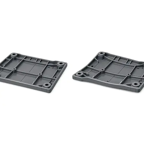
Flatness is often harder than size
Flatness causes trouble in many molded parts, especially large covers, frames, panels, and appearance surfaces. A part may measure close to its nominal length and width while still rocking, bowing, or twisting in assembly. From the customer’s point of view, that is still a dimensional failure.
Broad plastic surfaces are sensitive to cooling imbalance, shrink differences, wall variation, rib layout, and internal stress. That is why flatness usually needs its own review rather than being treated as a routine note on the drawing.
If a surface has to stay flat, the design often needs more structural planning than expected. Rib support, consistent walls, sensible gate placement, and realistic acceptance criteria matter much more than simply tightening the print. A flatness target can be achievable, but it has to be supported by the part design.
Holes, bosses, and snap-fit features need closer review
Some features deserve extra attention because they are more sensitive to local molding conditions. Holes may shift slightly, bosses may pull surrounding walls, and snap-fit elements may stack up small dimensional changes that affect the way the assembly feels in real use.
These features are often the ones that decide whether the part works. A latch location, a locating hole, a sealing land, or a mating tab may matter far more than an outside length that looks important on the drawing but does not actually control assembly. That is why function should lead the tolerance review.
An experienced supplier will usually separate critical features from general dimensions before tooling starts. That avoids the common problem of over-tolerancing the entire drawing when only a few features truly need tighter control.
How critical dimensions should be reviewed before tooling
Before tooling starts, the most important step is identifying which dimensions actually control fit, sealing, alignment, latching, or cosmetic appearance in the final product. Not every number on the drawing carries the same weight, and treating them all the same usually creates unnecessary tooling difficulty and avoidable cost.
In a practical DFM review, critical dimensions are usually checked together with the part structure, material behavior, shrink risk, and feature location. A mating boss, a sealing edge, a front cosmetic gap, or a snap-fit area should be reviewed very differently from a hidden wall or a non-functional outside profile.
At this stage, the goal is not just to approve the print. The goal is to decide what is realistic for stable production. That may mean widening non-critical tolerances, improving wall balance, adjusting geometry near sensitive features, or flagging a few dimensions that should not remain as-molded.
That review is where a good plastic parts supplier adds value. The right feedback before tooling is far cheaper than repeated tool changes after sampling begins.
When secondary machining is the better choice
Some features are simply better handled after molding. Tight bores, sealing surfaces, precise alignment features, and certain fit-critical details may be possible as molded in some parts, but not always in a stable or economical way.
Choosing secondary machining does not mean the molding process failed. In many projects, it is the more practical engineering decision. The main part geometry is molded for speed and cost efficiency, while one or two key areas are finished afterward to protect fit and consistency.
This kind of decision should be made early. If the drawing includes very tight dimensions in areas that are sensitive to shrinkage or distortion, it is better to identify them during DFM than to wait until repeated sampling makes the problem obvious.
What should be checked before releasing a part for tooling
Before a plastic part moves into tooling, a few questions are worth settling clearly. Which dimensions control assembly. Which surfaces are cosmetic. Which areas are most likely to move because of shrinkage or wall imbalance. Whether the selected resin supports the required tolerance level. Whether the drawing already reflects necessary draft, molding conditions, and realistic inspection strategy.
This review does more than improve moldability. It helps prevent expensive revisions later, especially on parts that combine appearance requirements with fit-critical features. Many production issues do not start with poor molding. They start with incomplete tolerance planning.
When these points are reviewed early, the project usually moves faster through sampling and into production with fewer surprises.
How to specify realistic tolerances on plastic part drawings
The best molded-part drawings do not apply the same tight tolerance across every feature. They identify the dimensions that truly affect function and allow the rest of the part to follow a more practical commercial range. That approach improves production stability and avoids unnecessary cost.
A good drawing also matches the tolerance to the material and the geometry. If the part uses PP, long unsupported walls, or broad flat faces, the tolerance strategy should reflect that reality. If the part uses ABS and the geometry is compact and stable, tighter control may be more realistic.
Another important point is measurement itself. Flexible plastic parts, textured surfaces, and thin walls can be difficult to inspect consistently if the measurement method is not defined clearly. A caliper reading on a soft feature may not tell the same story as a controlled fixture or a CMM check. For parts with tight functional requirements, the measurement plan matters almost as much as the tolerance value.
Conclusion
Injection molding can deliver very consistent plastic parts, but realistic tolerances always depend on more than the mold. Part size, material behavior, wall thickness, flatness risk, feature type, and inspection method all influence what can be held reliably in production.
Some parts are naturally stable. Some need design changes before tooling. Some critical features are better protected through secondary machining. The most effective projects are the ones that separate truly critical dimensions from general dimensions and solve tolerance risk before the tool is cut.
If your team is evaluating a plastic housing, bracket, cap, internal component, or cosmetic molded part and the drawing includes tight or function-critical dimensions, JeekMould can help review the tolerance risk before tooling starts. Sending the 3D CAD file and 2D drawing early makes it much easier to identify which tolerances are realistic, which features need special attention, and whether any design changes should be considered before production moves forward.
FAQs
1. What tolerance is realistic for an injection molded plastic part?
A realistic tolerance depends on part size, material, wall thickness, and geometry. Small molded features are usually easier to control than large plastic parts, while flat surfaces and long dimensions often need more tolerance allowance.
2. Which plastic materials are easier to hold tight tolerances with?
Amorphous materials such as ABS, PC, and PC/ABS are usually easier to control dimensionally than semi-crystalline materials such as PP, PA, and POM. Material shrinkage behavior has a direct effect on dimensional stability after molding.
3. Why do molded plastic parts go out of tolerance even when the mold is accurate?
The mold may be machined accurately, but the plastic part still changes during filling, packing, cooling, shrinkage, and ejection. That is why final part tolerance depends on both tooling accuracy and resin behavior in production.
4. Is flatness harder to control than linear dimensions in injection molding?
Yes. Flatness is often more difficult to control than simple length or width dimensions because large surfaces are more sensitive to uneven cooling, wall variation, internal stress, and warpage.
5. When is secondary machining needed after injection molding?
Secondary machining is often the better choice when a part includes tight bores, sealing surfaces, alignment features, or other critical dimensions that are difficult to keep stable as-molded in production.