
PEEK (polyether ether ketone) is a high-performance semi-crystalline polymer known for maintaining structural integrity under continuous heat, chemical exposure, mechanical load, and repeated fatigue cycles. Engineers choose PEEK not for cost savings but for its predictable behavior in demanding environments—stable modulus, extremely low creep, strong fatigue resistance, and wear performance that surpasses most engineering plastics.
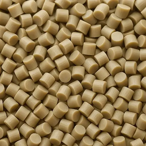
In an injection molding environment, PEEK behaves differently from conventional resins. The material requires higher thermal energy, tighter crystallization control, elevated mold temperatures, and a design approach aligned with how the polymer actually responds to heat and cooling. Understanding these behaviors is the foundation for getting stable, reliable results from PEEK-molded components.
What Is PEEK Injection Molding?
PEEK injection molding involves forming this semi-crystalline polymer at high melt temperatures (360–400°C) and high mold temperatures (160–200°C) so that crystallization can occur properly. Unlike typical thermoplastics, PEEK’s filling behavior, surface quality, solidification pattern, and final mechanical properties are largely driven by material conditions rather than machine adjustments.

PEEK Material Properties
Typical values for injection-molding grades (unfilled and GF30 reinforced)
| Property | Unfilled PEEK | GF30 PEEK | Notes |
|---|---|---|---|
| Melt Temperature (Tm) | ~343°C | ~343°C | Fundamental crystalline melting point |
| Recommended Melt Processing Range | 360–400°C | 370–400°C | Higher ranges improve flow stability |
| Mold Temperature | 160–200°C | 160–200°C | Drives crystallization and final strength |
| Density | 1.30 g/cm³ | 1.51 g/cm³ | GF reinforcement increases density |
| Tensile Strength | 95–100 MPa | 135–140 MPa | Fiber alignment influences directionality |
| Tensile Modulus | 3.6 GPa | 6.5–7.5 GPa | GF increases stiffness dramatically |
| Heat Deflection Temperature | ~160°C | ~300°C | Depends on crystallinity and fiber content |
| Continuous Service Temperature | 240–260°C | 240–260°C | Long-term stability with low creep |
| Shrinkage | 1.1–1.5% | 0.2–0.5% | Strongly influenced by wall-thickness & cooling |
| Water Absorption | <0.1% | <0.1% | Supports excellent dimensional stability |
PEEK’s molding behavior is shaped by several material-specific tendencies
PEEK Melt Temperature Requirements
PEEK maintains relatively high viscosity even at elevated melt temperatures, so the polymer chains require substantial thermal energy to relax and flow consistently. When melt temperature is even slightly below the ideal window, the flow front loses stability—breaking, freezing, or creating coarse surface texture. These behaviors signal insufficient melt energy rather than pressure issues. Most molding operations keep the melt between 360–400°C to allow smooth, uninterrupted filling.
PEEK Mold Temperature and Crystallization Behavior
PEEK’s mechanical strength and dimensional stability depend heavily on achieving the proper crystalline structure. That crystallization process only occurs at elevated mold temperatures. If the mold temperature drops too low, the part may show dull or hazy surfaces, weak layer formation, or unpredictable shrink patterns. Maintaining 160–200°C helps the crystalline regions develop as intended, which improves strength and surface quality while keeping dimensional drift under control.
How Cooling Rate Shapes PEEK Part Structure
PEEK does not freeze immediately like amorphous plastics; its solidification is governed by crystallization. When all regions cool at similar rates, the internal structure remains uniform and shrinkage stays predictable. When cooling varies significantly within the part, internal stress gradients form, leading to bending, twisting, or localized distortion. GF-reinforced PEEK amplifies this sensitivity because fiber orientation interacts with cooling rate differences and influences final shape.
PEEK’s Sensitivity to Shear During Molding
While PEEK withstands high temperatures, it responds aggressively to localized shear. Narrow gates, sudden cross-section transitions, or tight flow paths can generate enough shear heat to scorch the polymer, creating burn marks, dark streaks, or weak weld lines. These defects often resemble trapped-air burns, but the root cause is typically shear concentration rather than ventilation issues. Gate and flow-channel geometry must be sized to prevent local overheating.
Dimensional Behavior and Wall-Thickness Effects in PEEK
PEEK’s shrinkage is strongly influenced by crystallinity, wall-thickness distribution, and fiber orientation in reinforced grades. Thin sections cool quickly and shrink less; thick sections cool slower and shrink more. These differences can produce predictable but significant deformation trends such as bending or edge lift. Precision parts require careful planning of wall-thickness transitions, rib direction, and gate placement so that the material’s natural shrink patterns align with the intended geometry.
Material Behavior in PEEK Injection Molding
PEEK reflects the classic behavior of semi-crystalline polymers: flow stability, crystallization rate, and cooling balance work together to determine the part’s final properties. When any of these stages fall outside a stable window, the molded part will immediately reveal the underlying imbalance through surface features or dimensional drift.
Melt Behavior
Even when processed at high melt temperatures, PEEK remains viscous and requires uniform shear and consistent thermal distribution to fill the cavity reliably. Minor temperature variations disrupt the flow front, producing short shots, surface waviness, or poor fusion in transitions. Melt behavior often serves as the earliest indication of whether the material has received enough thermal energy.
Crystallization Behavior
PEEK’s mechanical and thermal performance rises sharply with increased crystallinity. High mold temperatures promote thorough crystallization and higher strength, but they also increase overall shrinkage. Conversely, inadequate mold temperature produces low-crystallinity parts with dull surfaces, soft layer transitions, and more dimensional wander. A mold running below 160°C simply cannot develop PEEK’s intended properties.
Cooling Behavior
Cooling dominates how internal structure and shrinkage gradients develop. Balanced cooling reduces warpage and helps align shrinkage with mold compensation. Uneven cooling creates stress gradients that distort the part in predictable directions—frequently amplified when glass fibers are present. The combination of cooling distribution and flow paths often determines the final deformation pattern.
Shrinkage and Warpage Characteristics
Unfilled PEEK typically shrinks 1.1–1.5%, whereas GF30 reinforced grades shrink only 0.2–0.5%. These numbers reflect two different deformation modes: unfilled grades shrink more uniformly yet unpredictably, while reinforced grades shrink directionally based on fiber alignment.
Warpage rarely has a single cause. Fiber orientation pulls shrinkage in specific directions; wall-thickness transitions introduce cooling differences; local hot and cold spots shift crystallization timing; and flow direction may not align with the structural design. These factors interact to determine whether a part bends globally, twists locally, or lifts at certain corners.
GF30 PEEK is often chosen for dimensional stability, but reinforced grades still depend on gate location, flow direction, and cooling uniformity. Reinforcement makes behavior more predictable—not automatically stable. Proper design is still required.
Design Considerations for PEEK Injection Molding
Designing PEEK parts using general engineering-plastic assumptions almost always leads to downstream corrections. Crystallization, shrinkage, and fiber orientation dominate how the part behaves, so design must align with material reality from the start.
Wall-thickness transitions are a major influence on warpage. Thick sections cool slowly and crystallize differently from thin sections, producing uneven shrinkage and internal stress. Uniform wall thickness, rib-based stiffening, and space for targeted mold cooling can significantly improve stability in load-bearing housings or multi-cavity parts.
Gate placement and flow direction must also reflect material behavior. In unfilled PEEK, flow direction sets shrinkage tendencies; in GF-filled grades, flow aligns fibers and essentially sets stiffness direction. If a part must carry load along a specific axis, the gate should encourage flow—and therefore fiber orientation—along that path. Ignoring this relationship often results in strength concentrated in the wrong direction.
Geometric details matter as well. Because PEEK parts eject at higher mold temperatures, sharp corners, thin edges, and abrupt transitions increase stress concentration and risk drag marks. Smooth transitions, generous radii, and adequate draft angles help the part crystallize uniformly and resist long-term dimensional drift.
Material-Driven Defect Tendencies
Short Shot
Short shots occur when melt or mold temperature is too low for the flow front to maintain continuity. This issue is rarely about pressure; it reflects insufficient thermal energy stored in the melt.
Burn Marks
Localized shear—not trapped gas—is the most common cause. Tight gate sections or sudden restrictions generate excess heat that discolors or degrades the polymer.
Weld Line Weakness
Two melt fronts must meet at high temperature to achieve molecular fusion. If either cools prematurely, the interface becomes weak and prone to fatigue failure.
Black Specks
Dark inclusions typically result from localized degradation or old material re-entering the melt, a condition very similar to what is seen in Black Specks in Injection Molding. PEEK’s high processing temperature amplifies even small amounts of thermal damage.
Applications of Peek injection molded parts
Medical-Grade Structural Implants
PEEK provides a stable modulus, fatigue resistance, and repeatable dimensions even after sterilization cycles. Its low moisture uptake ensures reliable fit and long-term predictability.
Aerospace and Avionics Insulation Components
The material withstands temperature cycling, vibration, and exposure to aviation fluids, making it suitable for lightweight insulation carriers and functional electronic housings.
High-Voltage Connector Carriers
PEEK maintains dielectric strength and structural integrity under continuous heat and electrical load. Clearances and locking features remain stable even in elevated-temperature environments.
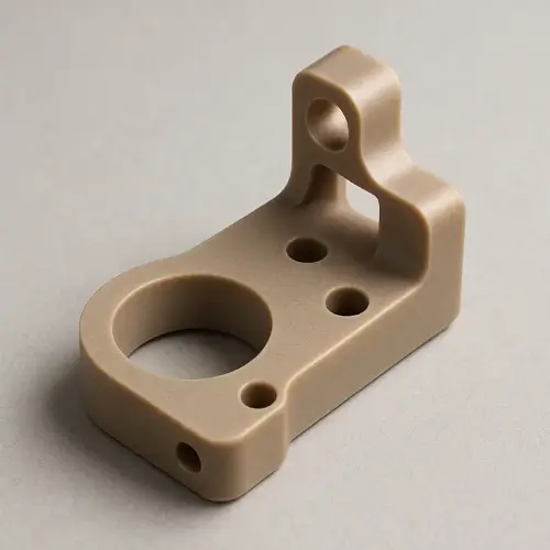
Precision Gears and Wear-Resistant Components
Low friction, wear resistance, and strong fatigue performance make PEEK ideal for small gears, sliders, and bearing retainers, particularly in reinforced grades with directional stiffness.
Valve Bodies and Fluid-Control Components
PEEK tolerates hot water, steam, and aggressive chemicals while maintaining consistent dimensions. This makes it a strong fit for sealing components and precision control structures.
High-Temperature Structural Parts
The polymer retains strength under sustained heat and mechanical load, providing metal-like stability with the benefits of low weight and design freedom.
Conclusion
PEEK’s injection-molding behavior is shaped by its melt viscosity, crystallization characteristics, cooling balance, and—when reinforced—fiber orientation. When these factors guide both part design and molding strategy, PEEK delivers a combination of structural reliability and thermal endurance that few polymers can match.
PEEK’s value lies in its long-term reliability and predictable performance. If you are designing precision components that require extreme heat resistance, chemical inertness, or high wear performance, contact our engineering team immediately.
Click here to receive a consultation on your customized PEEK component design and a precise quote!
FAQs
What makes PEEK harder to mold than typical engineering plastics?
Its high melt viscosity and reliance on crystallization make the process highly sensitive to temperature stability. Small shifts in melt or mold temperature can disrupt the flow front and affect part quality.
Why does PEEK require such a high mold temperature?
Full crystallization only occurs at elevated mold temperatures. Running the mold too cold produces low-crystallinity parts with weak layers and dimensional drift.
Does glass-fiber reinforcement improve dimensional stability?
GF30 reduces shrinkage and improves predictability, but fiber orientation introduces directional deformation. Proper gate placement and flow planning are still essential.
Why do PEEK parts show burn marks or dark spots?
Localized shear is often the cause. Tight gates, cross-section reductions, or abrupt flow turns generate excess heat that leads to discoloration or degradation.
How predictable is PEEK shrinkage during tool development?
Base shrink values are known, but real behavior depends on cooling uniformity, wall transitions, crystallinity, and flow direction. Compensation must reflect the part’s geometry.
Can PEEK maintain performance under continuous high temperature?
Yes—provided crystallization is adequate. When properly molded, PEEK exhibits extremely low creep and long-term structural stability.
Is PEEK suitable for thin-wall injection molding?
It can be, but thermal management becomes critical. Thin walls shed heat quickly, increasing the likelihood of short shots or weak weld lines. Larger gates and uniform mold temperature help maintain melt energy.