
Injection molding wall thickness affects mold filling, cooling, shrinkage, surface appearance, dimensional stability, and production cost. It is one of the first design details that should be reviewed before an injection mold is manufactured.
Most conventional injection molded parts use a nominal wall thickness between 1 and 3 mm, but this is only a starting range. Small connectors may use walls below 1 mm, while large industrial housings may require thicker walls, ribs, or other structural features.
Making every wall thicker does not automatically make a plastic part stronger. Excessive thickness can create sink marks, internal voids, uneven shrinkage, and longer molding cycles. Walls that are too thin may freeze before the cavity is filled, causing short shots, weak weld lines, flow marks, or excessive injection pressure.
A practical plastic part normally uses a suitable nominal wall thickness, keeps thickness changes gradual, and adds ribs or structural geometry where more stiffness is required.
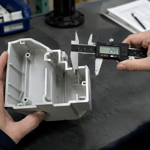
What Is Wall Thickness in Injection Molding?
Wall thickness is the distance between the inner and outer surfaces of an injection molded plastic part. The nominal wall thickness is the main or most frequently used thickness across the product.
For example, a plastic enclosure may use a 2 mm nominal wall. Its ribs, screw bosses, snap fits, mounting pads, and corner radii are then designed in relation to that base dimension.
Wall thickness is not only a product measurement. It also affects how molten plastic flows through the mold cavity and how quickly the molded part cools. A thin section creates more flow resistance and freezes faster, while a thick section retains heat and continues shrinking for longer.
Injection molding wall thickness should therefore be reviewed together with the plastic material, part size, flow length, gate position, surface requirements, mechanical loads, and expected production volume.
A wall thickness that works for a small ABS cover may not be suitable for a large glass-filled nylon housing, even when both parts have a similar overall shape.
What Is the Recommended Wall Thickness for Injection Molded Parts?
A nominal wall thickness of approximately 1.2 to 3 mm is a practical starting point for many general-purpose injection molded parts.
Small electronic housings may use thinner walls to reduce weight and save internal space. Larger covers and industrial components may require thicker walls or additional ribs to control flexing. Parts with long flow paths may also require greater thickness than compact parts made from the same resin.
| Part Type | Common Starting Wall Thickness |
|---|---|
| Small electronic housing | 1.0–2.0 mm |
| Consumer product enclosure | 1.5–2.5 mm |
| Automotive interior part | 1.8–3.0 mm |
| Medical device housing | 1.2–2.5 mm |
| Industrial equipment cover | 2.0–4.0 mm |
| Small precision connector | 0.5–1.5 mm |
| Structural plastic bracket | 2.0–4.0 mm with ribs |
These figures are preliminary design ranges rather than fixed molding limits. The required thickness may change when the part becomes larger, the gate is farther away, the resin grade changes, or the product requires a high-quality appearance surface.
The final injection molding wall thickness should be confirmed through material data, part design review, mold design, and trial molding.
Injection Molding Wall Thickness by Plastic Material
Different plastics have different melt viscosity, flow behavior, shrinkage, stiffness, and cooling requirements. The selected resin therefore affects both the minimum practical thickness and the risk associated with heavy sections.
| Plastic Material | Typical Starting Wall Thickness |
|---|---|
| ABS | 1.2–3.5 mm |
| Polycarbonate, PC | 1.0–4.0 mm |
| Polypropylene, PP | 0.8–3.8 mm |
| Polyethylene, PE | 0.8–5.0 mm |
| Nylon, PA | 0.8–3.0 mm |
| Acetal, POM | 0.8–3.2 mm |
| Acrylic, PMMA | 1.0–4.0 mm |
| PBT | 0.8–3.0 mm |
| PPS | 0.5–5.0 mm |
These values are typical design starting ranges, not fixed processing limits. The final thickness should be checked against the datasheet for the selected resin grade.
Two grades from the same plastic family may behave differently during molding. A high-flow ABS grade may fill a thinner section more easily than a standard ABS grade. Glass fiber, mineral filler, flame retardant, colorant, and recycled content can also change melt flow, shrinkage, and surface appearance.
Material-specific review becomes particularly important when the design approaches the lower end of the range, contains a long flow path, or uses transparent, reinforced, or highly cosmetic plastic.
Minimum Wall Thickness for Injection Molding
The minimum wall thickness is the thinnest section that can be filled repeatedly without unstable processing or unacceptable molding defects.
Some small components can be molded with walls below 1 mm, especially when a high-flow resin is used and the gate is positioned close to the thin section. However, wall thickness cannot be evaluated without considering how far the melt must travel.
A 0.8 mm wall located near the gate may fill without difficulty. The same 0.8 mm wall at the end of a large enclosure may freeze before the molten plastic reaches the final section.
Flow Length-to-Thickness Ratio
The flow length-to-thickness ratio describes the relationship between the distance the plastic must travel and the thickness of the cavity.
A long flow path combined with a thin wall creates greater resistance and faster heat loss. Resin flow grade, gate size, mold temperature, injection speed, venting, and part geometry all affect the acceptable ratio.
There is no single ratio that applies to every plastic. A high-flow polypropylene grade may fill a geometry that would be difficult for a more viscous polycarbonate or reinforced nylon.
This is why the minimum wall thickness should be reviewed using the actual resin grade and complete part geometry rather than a general thickness table alone.
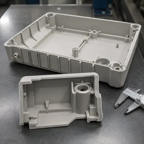
Thin Wall Injection Molding Problems
A thin section may require higher injection speed, higher pressure, or a higher mold temperature. These adjustments can improve filling, but excessive pressure may also cause flash, molded-in stress, material degradation, or difficult mold release.
Typical signs that a wall is too thin include incomplete filling, weak weld lines, hesitation marks, flow marks, and small ribs or corners that do not form consistently. Burn marks may also appear when trapped air cannot escape quickly enough from the final filling area.
Multi-cavity molds can show additional variation. One cavity may fill completely while another remains short because the design is already close to the resin’s flow limit.
When thin walls are necessary, the design may require a shorter flow path, a larger or relocated gate, improved venting, a higher-flow material, or mold-flow analysis.
The end-use performance should also be checked. A part may fill successfully but still flex excessively, crack during screw assembly, or deform when exposed to heat.
Maximum Wall Thickness for Injection Molding
Injection molding does not have one universal maximum wall thickness. Heavy plastic sections can be produced, but they usually require longer cooling and tighter process control.
For many common thermoplastics, local sections above approximately 4 to 5 mm deserve additional review. The plastic close to the mold surface cools first, while the center remains hot and continues to contract.
If packing pressure cannot compensate for this internal shrinkage, the surface may pull inward and form a sink mark. In other cases, the outside surface remains acceptable but a void forms inside the plastic.
Problems With Excessive Wall Thickness in Injection Molding
Excessive wall thickness increases part weight and resin consumption. It also keeps the mold closed for longer because the center of the heavy section must cool enough to resist deformation during ejection.
A part with unnecessary heavy sections may show dimensional changes after molding because the interior continues cooling outside the mold. This can be especially noticeable around mounting pads, large corners, and solid bosses.
When a component needs more stiffness, increasing the complete wall is often less effective than adding ribs, gussets, curves, or boxed sections. Heavy mounting areas can also be cored out so that the local thickness remains closer to the nominal wall.
Thick-wall injection molding may still be necessary for optical components, fluid-handling parts, electrical insulation, protective components, or products exposed to pressure and impact. These applications require material-specific mold design and processing rather than general enclosure rules.
How Wall Thickness Causes Sink Marks and Internal Voids
Sink marks are shallow depressions that appear when a thick internal section cools and contracts. They are commonly found opposite ribs, bosses, mounting pads, and heavy intersections.
Internal voids develop for a similar reason. Instead of pulling the outside surface inward, the contracting material leaves an empty space inside the part.
A rib that is nearly as thick as the main wall can create a visible sink mark on the opposite surface. A solid boss connected directly to a cosmetic wall can create the same problem. Several smaller features may also form a heavy section when they overlap in one location.
Increasing packing pressure can sometimes reduce a sink mark, but excessive packing may cause flash, stress, or dimensional changes elsewhere. Correcting the geometry is usually more stable than relying on molding parameters.
For visible surfaces, ribs and bosses normally use a lower thickness than the nominal wall. Dark colors, glossy finishes, and direct lighting make minor sink marks easier to see, so the feature thickness may need to be reduced further.
Uniform Wall Thickness and Wall Thickness Transitions
Uniform wall thickness helps molten plastic move through the mold cavity at a consistent rate. It also allows different areas of the part to cool and shrink more evenly.
When a thick area is connected directly to a thin wall, the thin section may solidify while the thick section remains hot. This difference in cooling time can create sink marks, dimensional variation, or warpage.
Uniform walls also help packing pressure reach the remaining areas of the cavity. If a narrow section freezes too early, it can block pressure from reaching a thicker area farther from the gate.
Perfectly equal wall thickness is not possible in every product. Sealing areas, mounting features, structural zones, and assembly interfaces may require local changes. The goal is to remove unnecessary differences and make required transitions gradual.
For example, changing directly from a 1.5 mm wall to a 4 mm block creates a local heavy section. A gradual taper gives the melt a smoother path and reduces the amount of material concentrated in one location.
Heavy mounting pads should be cored where possible. Solid bosses should not be placed directly against thin appearance walls, and the intersections of several ribs should be checked for hidden material buildup.
Corner radii must also be designed carefully. Adding only an internal radius can make the corner thicker than the adjoining walls. The outside surface should follow the inside radius so the total corner thickness remains reasonably consistent.
How Wall Thickness Affects Warpage and Shrinkage
Warpage occurs when different areas of a molded part shrink by different amounts or in different directions. Uneven wall thickness is one possible cause, but gate position, cooling-channel layout, mold temperature, material orientation, and ejection also affect the final shape.
A heavy section may remain soft when the surrounding walls are ejected. As it continues cooling outside the mold, it can pull the part toward one side.
Large flat components are particularly sensitive because a small difference in shrinkage can become visible across a long surface. Keeping the nominal wall reasonably uniform and arranging ribs symmetrically can reduce differences in cooling and stiffness.
Gate positions should support balanced filling rather than pushing the melt strongly through one side of the part. Mold temperature and ejection should also remain consistent across the cavity. If one side cools faster or releases earlier, the product may bend after ejection.
Glass-filled materials require additional attention. Fibers become oriented by melt flow, so shrinkage in the flow direction may differ from shrinkage across the flow direction. A wall thickness change can alter the local flow pattern and make warpage more difficult to predict.
Wall thickness should therefore be reviewed together with gate location, rib layout, cooling design, material shrinkage, and the complete filling pattern.
Injection Molding Rib and Boss Thickness Guidelines
Ribs and bosses add stiffness and assembly features without requiring the entire part to become thicker. Their dimensions should be related to the nominal wall thickness.
Rib Thickness
A rib thickness around 40–60% of the nominal wall thickness is a common starting range.
For a part with a 2 mm nominal wall, the initial rib thickness may be approximately 0.8–1.2 mm. The final value depends on material shrinkage, rib height, surface requirements, and the stiffness required.
A highly visible surface or a resin with higher shrinkage may require a thinner rib. Several properly spaced ribs are often more effective than one heavy rib.
Draft should be added so the rib can release from the mold, and the rib base should include a suitable radius. A rib that is too tall and thin may be difficult to fill or may bend during ejection.
Boss Wall Thickness
Screw bosses should normally be cored rather than molded as solid posts. A solid boss contains too much material and can produce sink marks or internal voids.
The boss wall should be related to both the nominal part wall and the screw or insert being used. When additional support is required, ribs or gussets can connect the boss to nearby walls.
The supporting features should not overlap in a way that creates another heavy intersection.
Corner Thickness
Sharp internal corners restrict material flow and concentrate stress. Adding a suitable internal radius improves filling and part strength.
The outside surface should follow the inside radius so the corner thickness remains close to the surrounding wall. Otherwise, the corner may become a hidden heavy section and develop sink marks or uneven shrinkage.
Wall Thickness DFM Example
Consider a plastic housing with a 2 mm nominal wall and a screw mounting area containing a solid section almost 5 mm thick.
The heavy section may create a visible sink mark on the outside surface and increase cooling time. Increasing packing pressure may reduce the sink mark temporarily, but it does not remove the excessive material.
A more stable design is to core the mounting area so its wall is closer to the nominal thickness. Support ribs can then connect the boss to the side wall and restore the required stiffness.
This type of change keeps the assembly function while reducing local material mass, sink-mark risk, and cooling time. It also shows why wall thickness should be reviewed before mold steel is cut rather than corrected only through molding parameters.
How Wall Thickness Affects Cooling Time and Part Cost
Cooling is normally one of the longest stages in an injection molding cycle. The mold cannot open until the plastic part is stiff enough to resist deformation during ejection.
A thick section takes longer to cool because heat must travel farther from the center of the plastic to the mold surface. The relationship is not linear, so a small increase in wall thickness can produce a much larger increase in cooling time.
Longer cooling means fewer parts can be produced per hour. It also increases machine use, energy consumption, and the production cost allocated to each molded component.
Thicker walls use more resin as well. The difference may appear small on one part, but it becomes significant across thousands of molding cycles.
Reducing unnecessary thickness can lower both material cost and cycle cost. However, the revised design must still meet the required strength, impact resistance, sealing performance, assembly load, and operating temperature.
Wall thickness optimization should therefore remove non-functional material rather than simply making the entire product thinner.
How to Choose the Right Wall Thickness for a Plastic Part
The first step is to confirm the material family and, when possible, the exact resin grade. Melt flow can vary considerably between different grades of ABS, PC, PP, PA, POM, or other plastics. Glass fiber, mineral filler, flame retardant, and recycled content should also be identified.
The part requirements must then be reviewed. A housing may need to resist bending and impact, while a boss may need to withstand screw installation. Wall thickness should respond to the actual load rather than being increased uniformly without a clear reason.
A nominal wall can then be selected according to the material, overall part size, flow distance, and similar molded products. This base thickness becomes the reference for ribs, bosses, snap fits, corners, and mounting features.
The final review should examine long flow paths, remote thin sections, heavy intersections, visible surfaces, cooling balance, and ejection. Mold-flow analysis may be useful when the wall is thin, the part is large, or several gates must fill the cavity at the same time.
An injection molding DFM review can identify these risks while changes are still inexpensive. Once mold steel has been cut, correcting an unsuitable wall thickness can require welding, remachining, or replacing mold inserts.
What to Provide for an Injection Molding Quote
A molding supplier can review wall thickness more accurately when the quotation includes:
- 3D CAD model
- 2D drawing with critical tolerances
- Plastic material and preferred grade
- Required production quantity
- Surface finish and texture
- Part color
- Visible and non-visible surfaces
- Screw, insert, snap-fit, and assembly details
- Operating temperature
- Mechanical and chemical exposure
- Inspection or testing requirements
- Known concerns about sink marks, warpage, or thin sections
The supplier can then assess whether the proposed injection molding wall thickness is suitable for filling, cooling, appearance, dimensional control, and production volume.
Conclusion
Injection molding wall thickness must support mold filling, cooling, dimensional stability, surface appearance, and end-use performance at the same time.
Most general plastic parts start with a nominal wall between 1 and 3 mm, but the final dimension should be based on the selected resin grade, part size, flow length, gate location, and structural requirements.
Walls that are too thin may cause incomplete filling, weak weld lines, or unstable processing. Excessively thick sections increase the risk of sink marks, internal voids, uneven shrinkage, and longer molding cycles.
Keep the nominal wall reasonably uniform, use gradual transitions, and avoid solving every strength problem by adding solid material. Ribs, gussets, radii, and cored sections can improve stiffness while reducing weight, cooling time, and production cost.
JeekMould provides injection molding DFM review, mold manufacturing, material selection, trial molding, and plastic part production. Upload your 3D CAD model and 2D drawing to receive a wall-thickness review and injection molding quotation.